T Flip Flop Explained: Truth Table, Circuit, Working, and Applications
A T flip-flop, or Toggle flip-flop, is a fundamental building block in digital electronics. Flip-flops are bistable devices, meaning they have two stable states, representing binary values of 0 and 1. T flip-flops are widely used in digital systems for storing binary data, frequency division, and counters. They are a special type of flip-flop that can change or toggle their state on the application of a clock signal, making them ideal for sequential logic applications where changes are synchronized with a clock.
What is a T Flip Flop?
A T flip-flop is a type of flip-flop that toggles its output state with each clock pulse when the input, labeled ‘T,’ is set to 1. The term “Toggle” refers to the device’s behavior of switching its output between the two binary states. If the T input is 0, the output remains in its previous state, while if T is 1, the output toggles with each clock pulse.
Basic Functionality:
- When T = 0: The output (Q) retains its current state (no change).
- When T = 1: The output toggles, switching from 0 to 1 or from 1 to 0, with each clock pulse.
Differences from Other Flip-Flops:
- SR Flip-Flop: Has two inputs, Set (S) and Reset (R), to control the output. T flip-flop can be derived from SR by tying both inputs together.
- JK Flip-Flop: Similar to an SR flip-flop but does not have an invalid state. The T flip-flop can be considered a simplified JK flip-flop with J and K tied together.
- D Flip-Flop: Has a single input (D) that determines the next state. In contrast, a T flip-flop toggles based on the clock signal if T is high.
T Flip Flop Truth Table
The truth table for a T flip-flop illustrates the relationship between the T input, clock, and output.
| T (Input) | Clock (Trigger) | Q (Previous State) | Q (Next State) |
|---|---|---|---|
| 0 | ↑ | 0 | 0 |
| 0 | ↑ | 1 | 1 |
| 1 | ↑ | 0 | 1 |
| 1 | ↑ | 1 | 0 |
- The ‘↑’ symbol indicates a rising edge (positive edge) of the clock pulse.
- When T = 0, the output Q remains unchanged regardless of the previous state.
- When T = 1, the output Q toggles with every rising edge of the clock.
Toggling Concept:
“Toggling” means switching the output state from 0 to 1 or from 1 to 0. In T flip-flops, toggling occurs whenever the T input is high (1) and a clock pulse triggers the flip-flop. This characteristic makes T flip-flops suitable for creating binary counters, as each clock pulse effectively divides the frequency by two.
Circuit Diagram of a T Flip Flop
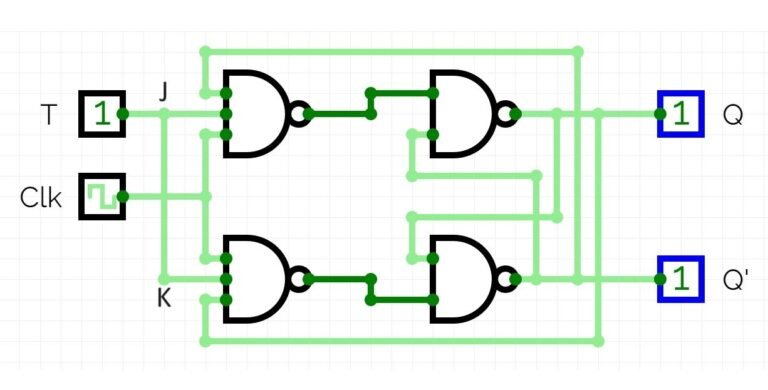
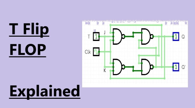
The basic circuit diagram of a T flip-flop can be constructed using a JK flip-flop by connecting the J and K inputs together to form a single T input.

Components Used:
- Logic Gates: Typically, NAND or NOR gates are used to build flip-flop circuits.
- Clock Input: Provides the triggering signal that causes the flip-flop to toggle its state.
- Feedback Connections: Used to maintain the internal state of the flip-flop.
Step-by-Step Working:
- When the Clock is Low (0): The state of the output remains unchanged, regardless of the T input.
- When the Clock has a Rising Edge (↑):
- If T = 0, the output Q retains its previous state.
- If T = 1, the output Q toggles from its current state to the opposite state.
- Feedback Mechanism: The internal feedback mechanism ensures that the output state is maintained until the next clock pulse.
Working of T Flip Flop
The operation of a T flip-flop is governed by its T input and clock signal.
Based on Clock and T Input:
- No Clock Pulse (Stable State): The output remains unchanged regardless of the T input.
- Clock Pulse Applied:
- If T = 0, the output remains in the current state (no change).
- If T = 1, the output toggles between 0 and 1 with each clock pulse.
Edge-Triggered and Level-Triggered T Flip-Flops:
- Edge-Triggered T Flip-Flop: Changes state only at the rising or falling edge of the clock pulse. Most digital systems use edge-triggered flip-flops to synchronize changes in the circuit.
- Level-Triggered T Flip-Flop: Responds to the level (high or low) of the clock signal. It is less common due to the potential for glitches when the clock is high for an extended period.
Designing T Flip Flop from Other Flip-Flops
A T flip-flop can be constructed using other types of flip-flops, such as JK or D flip-flops, by appropriately configuring their inputs.
6.1. Implementing T Flip-Flop Using JK Flip-Flop
To design a T flip-flop from a JK flip-flop:
- Connect the J and K inputs together to form a single input, T.
- When T = 0, both J and K are 0, so the output Q remains in its previous state (no change).
- When T = 1, both J and K are 1, causing the output Q to toggle with each clock pulse.
The resulting configuration functions as a T flip-flop, where the toggling occurs based on the T input.
6.2. Implementing T Flip-Flop Using D Flip-Flop
To implement a T flip-flop using a D flip-flop:
- Connect the D input to the output of an XOR gate, where the inputs to the XOR gate are the current output Q and the T input.
- The XOR operation ensures that when T = 1, the D input is the complement of Q, causing a toggle. When T = 0, the D input matches Q, keeping the output unchanged.
The configuration effectively transforms a D flip-flop into a T flip-flop by using simple combinational logic.
Applications of T Flip Flop
T flip-flops have several important applications in digital systems due to their ability to toggle states and divide frequencies.
7.1. Frequency Dividers
- T flip-flops can be used to divide the frequency of an input clock signal by two. This is achieved by toggling the output with each clock pulse, effectively halving the frequency.
7.2. Counters
- T flip-flops are commonly used in binary counters, where multiple flip-flops are connected in sequence to count clock pulses.
- In an n-bit counter, the first flip-flop toggles on each clock pulse, while the subsequent flip-flops toggle based on the state of the preceding flip-flop, creating a ripple effect.
7.3. Memory Elements
- T flip-flops can function as basic memory elements in sequential circuits, storing binary data (0 or 1).
- They are used in various types of storage registers to hold data temporarily.
7.4. Sequential Circuits
- T flip-flops play a significant role in the design of sequential circuits, where the output depends not only on the current inputs but also on the previous state.
- Examples include state machines, digital clocks, and data synchronization circuits.
Advantages and Limitations of T Flip Flop
8.1. Advantages
- Simple Design: T flip-flops have a straightforward structure and operation, making them easy to understand and implement in digital circuits.
- Frequency Division: They are ideal for dividing clock frequencies, which is useful in timing and counting applications.
- Counters and Registers: T flip-flops are commonly used in various counting and data storage applications, making them versatile in digital design.
8.2. Limitations
- Limited Control Inputs: Compared to JK or SR flip-flops, T flip-flops have fewer control options since they only toggle or hold the current state.
- Propagation Delay in Ripple Counters: When used in ripple counters, T flip-flops can introduce cumulative delays, limiting the speed of the counter.
- Susceptibility to Glitches: In level-triggered designs, T flip-flops may be prone to glitches, requiring careful clock signal management.
FAQs about T Flip Flop
Q1: What is the main function of a T flip-flop?
A: The main function of a T flip-flop is to toggle its output state with each clock pulse when the T input is high.
Q2: How can a T flip-flop be used as a frequency divider?
A: A T flip-flop can divide the frequency of an input clock by two, as it toggles its output with each clock pulse, effectively halving the frequency.
Q3: What is the difference between edge-triggered and level-triggered T flip-flops?
A: Edge-triggered T flip-flops change state only at the rising or falling edge of the clock pulse, while level-triggered T flip-flops respond to the high or low level of the clock signal.
Q4: Can a T flip-flop be constructed using a D flip-flop?
A: Yes, by connecting the D input to an XOR gate, with inputs from the T input and the current output Q.
Q5: What are the limitations of using T flip-flops in counters?
A: In ripple counters, T flip-flops can introduce propagation delays due to sequential toggling, limiting the speed of the counting operation.
Conclusion
In conclusion, The T flip-flop is a digital circuit component with widespread applications in counters, frequency dividers, and memory elements. Its simple toggling action based on clock pulses makes it essential for sequential circuit design. Understanding the operation, implementation, and applications of T flip-flops is crucial for designing efficient digital systems. Although T flip-flops have certain limitations, they remain a fundamental building block in digital electronics.


