ESP32_C6-Bug – RISC V Dev Board
An overview of the ESP32-C6-DevKitC-1-N8, an entry-level development board with the ESP32-C6-WROOM-1 module, is given in this article. The board supports Thread, Bluetooth 5, Zigbee, and Wi-Fi 6. It has all the necessary parts, including as LEDs, USB ports, a power regulator, and pin headers for simple connection. The ESP32-C6-WROOM-1 module has an SPI flash capacity of 8MB. The main characteristics of the board, including the RGB LED, Boot and Reset buttons, and USB Type-C port, are described in the article. This adaptable board provides a small and feature-rich development platform, making it ideal for a range of IoT and wireless communication applications.
Introduction
ESP32-C6-Bug, a small yet robust development board featuring the cutting-edge Esp32-C6FH4 RISC-V MCU from the ESP32 family. This versatile board is compatible with various wireless protocols, offers remarkable energy efficiency, has built-in battery support, and is well-suited for a diverse array of applications.
The ESP32-C6-Bug offers support for a range of wireless protocols, including Wi-Fi 6, BLE 5, Thread, and Zigbee. Its introduction of Wi-Fi 6 introduces new capabilities while optimizing energy usage, enabling the development of low-power, multi-protocol devices utilizing the Esp32-C6FH4 chip. This compact board is designed to neatly fit onto a breadboard and comes with castellated holes for easy integration into other products. Notable features include an integrated 32.768 kHz RTC oscillator and extremely low power consumption, as low as 20uA in sleep mode. The ESP32-C6-Bug can be programmed using both the Arduino framework and Esp-IDF, and a plethora of example links are readily available for reference.
Exciting Use-Case Possibilities
- Versatile Multi-Protocol USB Dongle (Similar to Home Assistant SkyConnect): With its native USB capabilities and support for a variety of wireless protocols, the Esp32-C6-Bug offers the potential to create a versatile USB dongle. This dongle can grant users access to Wi-Fi, Bluetooth, Thread, and Zigbee networks, simplifying connectivity for multiple devices.
- Bridging the Gap with Ethernet: To further expand its connectivity options, the Esp32-C6-Bug can serve as an Ethernet bridge. While it lacks native Ethernet RMII support, it is compatible with popular Ethernet chips like the W5500 via SPI, enabling seamless integration with wired networks.
- Empowering Esp32-C6-Bug Smart Home Devices: Forward-thinking developers are already experimenting with Esp32-C6 support in ESPHome, opening up a realm of possibilities for creating smart home devices with enhanced connectivity and features.
- Small, Battery-Powered Innovations: Whether you’re developing fitness trackers, motion capture systems, BLE speakers, or virtual reality controllers, the Esp32-C6-Bug is an excellent choice. Its built-in battery charge and protection support, coupled with the low-power capabilities of the Esp32-C6FH4 chip, make it an ideal solution for crafting compact, long-lasting, battery-powered devices. The Esp32-C6-Bug datasheet even includes a BLE demo, showcasing its suitability for these applications.
Proven Use-Cases
The Esp32-C6-Bug truly shines in scenarios that demand low-power functionality and multi-protocol capabilities. Its versatility makes it a prime choice for a variety of applications, including:
- Multi-Protocol Devices: The Esp32-C6-Bug is exceptionally well-suited for crafting devices that need to seamlessly operate across multiple wireless protocols, making it ideal for applications such as protocol bridges and multi-protocol gadgets.
- Wearable Electronics: Its energy-efficient design and support for different wireless standards make the Esp32-C6-Bug a great fit for wearable electronic devices, ensuring extended battery life and connectivity.
- Smart Home Innovations: The board’s compatibility with various wireless standards and low-power features positions it as a valuable asset for smart home device development.
Tested and Proven Examples:
- Thread to Wi-Fi Bridge: Espressif offers an excellent example demonstrating how to establish a bridge between Thread network devices and Wi-Fi using a single Esp32-C6-Bug board. Detailed testing and comprehensive descriptions are available in the Esp32-C6-Bug datasheet.
- Zigbee Light Bulbs and Switches: Espressif provides a well-documented example showcasing the creation of Zigbee devices like light bulbs and switches using the Esp32-C6-Bug. This example has undergone rigorous testing and is detailed in the Esp32-C6-Bug datasheet.
- Zigbee Sleepy Device: This particular example leverages the low-power sleep modes of the Esp32-C6-Bug in conjunction with the Zigbee protocol. It enables the development of battery-powered, low-power devices with Zigbee connectivity, achieving power consumption levels as low as 60uA when in sleep mode. Further information can be found in the Esp32-C6-Bug datasheet.
Features and Specifications
Chip Features:
- 32-bit RISC-V 160MHz processor
- 32-bit RISC-V 20MHz low-power processor
- 512 MB SRAM, 4MB Flash
- WiFi-6, BLE 5 + IEEE 802.15.4 radio (Zigbee, Thread, etc…)
- 2.4 GHz Wi-Fi 6 (802.11ax) radio also supports 802.11b/g/n for backward compatibility
- SPI, UART, I2C, I2S, RMT, TWAI, PWM, SDIO, Motor Control PWM, 12-bit ADC, and a temperature sensor.
Battery features:
- Under-voltage and reverse-polarity protection
- On-board battery charging and level measurement w/ indicator LED
- 20 uA deep sleep power consumption (with Timer wake-up)
Form-factor:
- Castellated holes
- Pin names on both sides
- Breadboard compatible
- Two M1 mounting holes
Mechanical features:
- User-controlled LEDs
- External 32.768 kHz RTC oscillator and 40 MHz oscillator
- Reset and user-controlled buttons
- 700 mA low-noise LDO
- USB-C for programming and communication
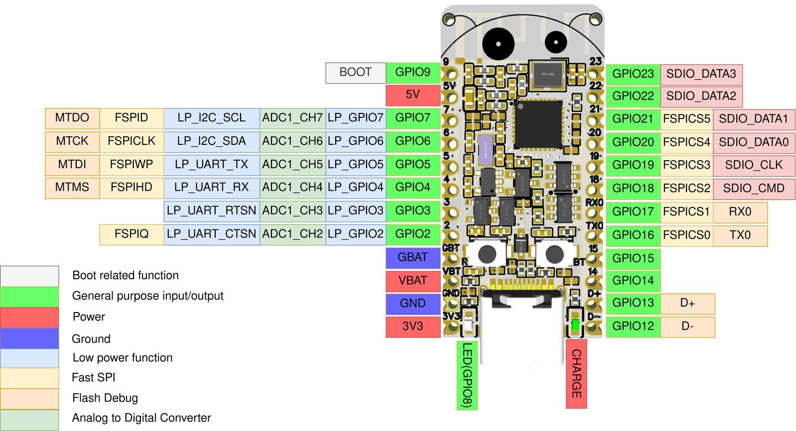
- 19 GPIOs exposed
ESP32-C6-DevKitC-1-N8
The ESP32-C6-DevKitC-1-N8 is an entry-level development board featuring the ESP32-C6-WROOM-1, a versatile Wi-Fi and Bluetooth Low Energy (BLE) RISC-V MCU module that seamlessly integrates complete Wi-Fi, Bluetooth LE, Zigbee, and Thread functionalities.
This version of the board is equipped with the ESP32-C6-WROOM-1 module, boasting 8MB of Flash memory for ample storage capacity.
The module conveniently breaks out most of its I/O pins to the pin headers on both sides of the board, facilitating easy interfacing. Developers have the flexibility to connect peripherals using jumper wires or securely mount the ESP32-C6-DevKitC-1-N8 on a breadboard for experimentation. Notably, it offers a debug UART/USB port and a separate native USB port, enabling seamless uploading, debugging, and USB-based interactions simultaneously.
The ESP32-C6, a 32-bit single-core RISC-V CPU with a maximum operating frequency of 160 MHz, is the central component of this module. It is also very energy-efficient since it has the capacity to turn off the CPU and use a low-power co-processor to continuously monitor peripherals. SPI, LCD, Camera interface, UART, I2C, I2S, remote control, pulse counter, LED PWM, USB Serial/JTAG controller, MCPWM, SDIO host, GDMA, TWAI® controller (compliant with ISO 11898-1), ADC, touch sensor, temperature sensor, timers, watchdogs, and support for up to 45 GPIOs are just a few of the many peripherals that the ESP32-C6 integrates. Furthermore, it has a full-speed USB 1.1 On-The-Go (OTG) interface that allows for USB connection.
For power supply, there are three mutually exclusive options:
- USB Type-C to UART Port (default and recommended)
- 5V and GND pin headers
- 3V3 and GND pin headers
Using the USB Type-C to UART Port is the preferred method for powering the board.
Key Components:
- ESP32-C6-WROOM-1: The ESP32-C6-WROOM-1 is a versatile module that supports Wi-Fi 6, Bluetooth 5, and IEEE 802.15.4 (Zigbee 3.0 and Thread). This module is centered around the ESP32-C6 chip and comes equipped with a PCB antenna as well as an 8 MB SPI flash for storage.
- 5V to 3.3V LDO: This component serves as a power regulator, converting a 5V power source into a stable 3.3V output, ensuring proper voltage levels for the board.
- 3.3V Power On LED: This LED indicator lights up when the board is powered via a USB connection, providing a visual indication of power availability.
- Pin Headers: The board features pin headers that break out all available GPIO pins (except those reserved for the SPI flash), making it convenient for easy interfacing and programming. Further details can be found in the Header Block section.
- USB-to-UART Port: A single USB-to-UART bridge chip is responsible for facilitating data transfer at speeds of up to 3 Mbps. This port serves as a communication channel with the board.
- ESP32-C6 USB Type-C Port: The USB Type-C port on the ESP32-C6 chip complies with USB 2.0 full-speed specifications, allowing for data transfer speeds of up to 12 Mbps. However, it’s important to note that this port does not support the higher-speed 480 Mbps high-speed transfer mode.
- Boot Button: The Boot button is used for initiating the Firmware Download mode when held down and pressed in conjunction with the Reset button. This mode enables the downloading of firmware through the serial port.
- Reset Button: Pressing this button triggers a system restart, providing a quick and convenient way to reset the board.
- USB-to-UART Bridge: This component supplies power to the board and establishes communication with the ESP32-C6 chip via the on-board USB-to-UART bridge.
- RGB LED: An addressable RGB LED, controlled by GPIO8, provides visual feedback and can display various colors and patterns.
- J5: This section serves for current measurement purposes and includes additional details in the Current Measurement section for reference.
Conclusion
In conclusion, the ESP32-C6 module, at the core of this development platform, represents a powerful and energy-efficient solution for a wide range of applications. With its 32-bit single-core RISC-V CPU, capable of operating at 160 MHz, it not only offers robust processing capabilities but also excels in power efficiency through its ability to leverage a low-power co-processor for peripheral monitoring. The integration of various peripherals, from SPI and UART to USB and GPIOs, positions the ESP32-C6 as a versatile choice for IoT and wireless communication projects. Its full-speed USB 1.1 On-The-Go (OTG) interface further enhances its connectivity, making it a valuable asset for developers and engineers seeking a feature-rich development platform.
Suggested Reads!