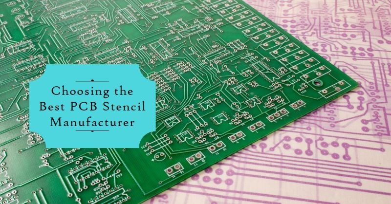
Avoid 10 Common PCB Hand Soldering Problems
Hand soldering is both a skill and an art form in the world of electronics manufacturing. While automated assembly processes have become increasingly prevalent there are still scenarios where hand soldering remains indispensable. Whether it’s prototyping, repair work or low-volume production. Mastering hand soldering is essential for electronics enthusiasts and professionals alike. However, it comes with its own set of challenges. In this blog post, we will discuss 10 common PCB hand soldering problems and provide tips on how to avoid them.
Common PCB Hand Soldering Problems
Here are some common PCB Hand Soldering Problems:
- Cold Solder Joints
- Solder Bridges
- Component Damage
- Insufficient Wetting
- Lifted Pads
- Tombstoning
- Component Misalignment
- Excessive Solder Splatter
- Inadequate Thermal Relief
- Inconsistent Soldering Quality
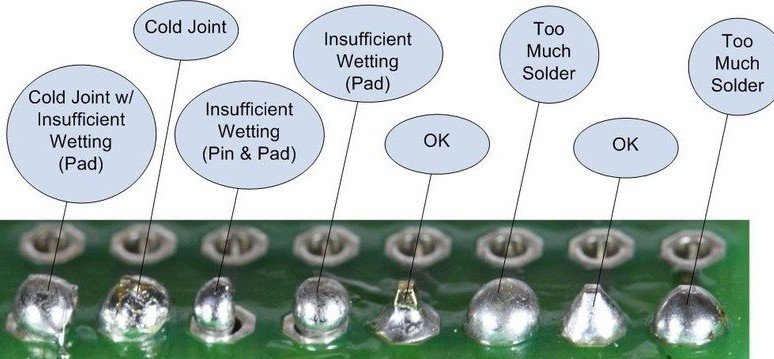
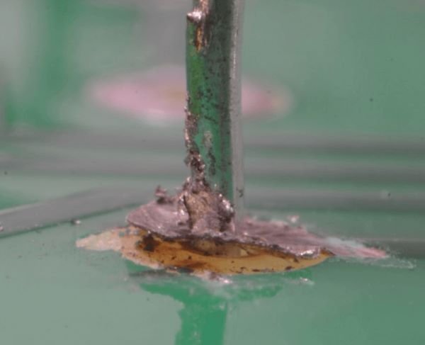
1. Cold Solder Joints
Cold solder joints occur when the solder used to connect components does not properly melt and bond with the metal surfaces. This can result in weak connections that are prone to failure over time. Cold solder joints can be caused by a variety of factors including insufficient heat during the soldering process, inadequate flux or improper technique.
Signs of Cold Solder Joints
- Visual Inspection: Cold solder joints may appear dull or grainy unlike properly soldered joints that have a smooth and shiny appearance.
- Intermittent Connections: If a circuit or device intermittently works or stops working. it could be due to cold solder joints that are not providing a consistent electrical connection.
- Physical Movement: Components that are not securely soldered may move or wiggle when touched indicating a weak connection.
- Electrical Issues: Cold solder joints can lead to various electrical problems. Such as intermittent power loss, signal distortion or device malfunction.
Preventing and Fixing Cold Solder Joints
- Proper Technique: Ensure that you are using the correct soldering technique including applying the right amount of heat and solder to create a strong bond.
- Quality Tools and Materials: Invest in high-quality soldering irons, solder and flux to ensure reliable connections.
- Practice: Soldering is a skill that improves with practice, so take the time to hone your technique.
- Inspect Your Work: After soldering, visually inspect your joints to ensure they have a smooth and shiny appearance.
If you do encounter cold solder joints, it is important to fix them promptly to avoid further issues. Here are some steps to follow:
- Identify the Cold Solder Joints: Use a magnifying glass if necessary to locate the joints that appear dull or grainy.
- Reheat and Resolder: Apply heat to the cold solder joint using a soldering iron allowing the solder to fully melt and bond with the metal surfaces.
- Inspect and Test: After resoldering, visually inspect the joint to ensure it has a smooth and shiny appearance. Test the connection to ensure it is now stable and reliable.
2. Solder Bridges
Solder bridges happen when excess solder forms a connection between two adjacent components or pads. This can cause short circuits and malfunctioning of the circuit. To prevent solder bridges, use the right amount of solder and ensure that it is properly controlled and applied only to the intended joint.
Effects of Solder Bridges
- Electrical shorts: Solder bridges create unintended connections between electrical points, causing electrical shorts. This can lead to malfunctioning circuits, overheating or even damage to the components.
- Malfunctioning or non-functional devices: When solder bridges occur, the intended electrical pathways on the circuit board are disrupted. This can result in devices not functioning as intended or not working at all.
- Interference with signal transmission: Solder bridges can interfere with the transmission of signals between components, leading to poor performance or complete failure of the device.
Preventing and Fixing Solder Bridges
- Use the right amount of solder: Practice good soldering technique by using the appropriate amount of solder. Avoid using excessive solder, as it increases the likelihood of solder bridges.
- Ensure proper component alignment: Take care to align components correctly before soldering. Misaligned components can lead to solder bridges.
- Use flux: Flux helps to remove oxides and impurities from the surfaces being soldered, improving the soldering process and reducing the chances of solder bridges.
- Inspect and clean the circuit board: Before soldering, inspect the circuit board for any contaminants or debris. Clean the board thoroughly to ensure a clean soldering surface.
- Use solder wick or desoldering pump: If solder bridges do occur, use solder wick or a desoldering pump to remove the excess solder and separate the unintended connections.9
3. Component Damage
During hand soldering, components can be easily damaged due to excessive heat or mechanical stress. To avoid component damage use a soldering iron with adjustable temperature settings and be gentle when handling the components. It is also helpful to use heat sinks or heat-resistant tape to protect sensitive components.
To ensure the integrity of your components, it is important to follow some best practices and take necessary precautions.
- Use a Soldering Iron with Adjustable Temperature Settings
- Be Gentle When Handling Components
- Use Heat Sinks or Heat-Resistant Tape
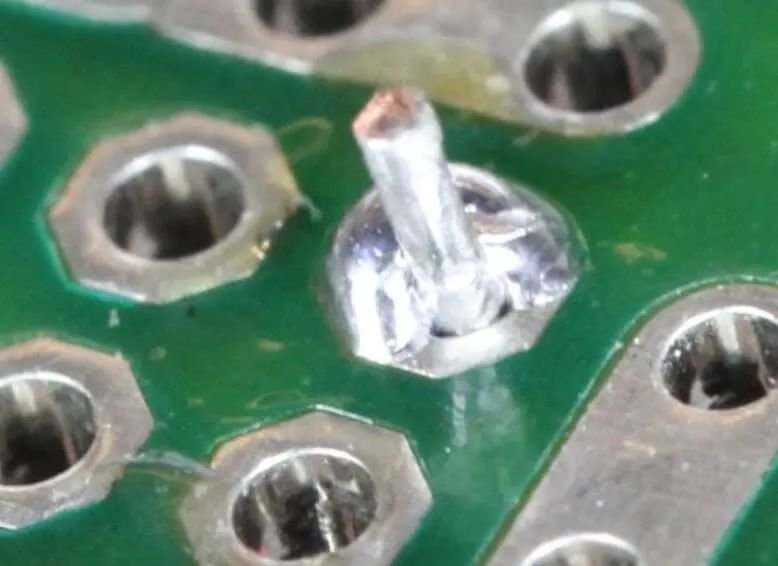
4. Insufficient Wetting
Insufficient wetting occurs when the solder does not properly adhere to the component leads or PCB pads. This can result in weak connections and unreliable circuitry. To ensure sufficient wetting, clean the component leads and PCB pads before soldering and use flux to improve the solder flow and wetting.
Solutions for Insufficient Wetting
- Clean the Component Leads and PCB Pads: Prior to soldering, it is essential to clean both the component leads and PCB pads to remove any contaminants. This can be done using isopropyl alcohol, a soft brush or a lint-free cloth.
- Use Flux: Applying a sufficient amount of flux to the solder joints can greatly enhance the wetting process. Flux helps to remove oxidation and other impurities, allowing the solder to flow more easily and adhere properly. Make sure to choose the appropriate flux for your soldering application and apply it evenly on the solder joints.
- Optimize Soldering Temperature: Using the correct soldering temperature is important for achieving sufficient wetting. Refer to the manufacturer’s guidelines or datasheets to determine the recommended temperature range for the components and soldering materials being used. It is also important to ensure that your soldering iron is properly calibrated and maintained.
- Practice Proper Soldering Techniques: Improving your soldering techniques can also contribute to better wetting. Make sure to apply the soldering iron tip to both the component lead and the PCB pad simultaneously to ensure even heat distribution. Allow the solder to flow smoothly and evenly onto the joint and avoid excessive heating or over-soldering.
- Consider Using Solder Paste: In some cases, using solder paste can help improve wetting, especially for surface mount components. Solder paste contains flux and solder particles, which can enhance the wetting process when heated. It is important to follow the manufacturer’s instructions when using solder paste.
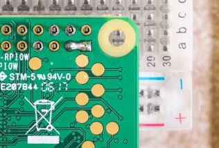
5. Lifted Pads
Lifted pads happen when excessive heat or mechanical stress causes the pads to detach from the PCB. This can lead to the loss of electrical connection and render the PCB unusable. To prevent lifted pads, use a soldering iron with adjustable temperature settings and avoid applying excessive force or heat to the pads.
Causes of Lifted Pads
- Excessive Heat: When the temperature is too high or the soldering iron is held on the pad for too long, it can weaken the bond between the pad and the PCB, leading to lifting.
- Mechanical Stress : This can occur during the assembly process when excessive force is applied to the pads or when the PCB is subjected to physical stress after assembly, such as bending or twisting.
Preventing Lifted Pads
1. Proper Soldering Technique
- Ensure that the soldering iron tip is clean and properly tinned.
- Use a soldering iron with adjustable temperature settings and set it to the appropriate level for the components you are working with.
- Apply solder to the pad and component lead simultaneously, ensuring good heat transfer and a strong bond.
- Avoid holding the soldering iron on the pad for too long, as this can lead to excessive heat and pad lifting.
2. Proper Handling and Support
- Handle the PCB with care, avoiding excessive force on the pads.
- Provide proper support for the PCB to prevent bending or twisting that could lead to pad lifting.
- Use appropriate tools and fixtures to hold the PCB securely during assembly.
3. Inspection and Quality Control
- Inspect the PCB after soldering to check for any signs of lifted pads.
- Perform electrical testing to ensure proper connectivity.
- Implement quality control measures to identify and address any issues during the manufacturing process.
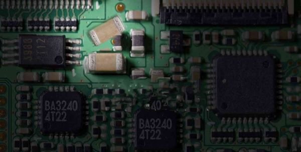
6. Tombstoning
Tombstoning occurs when a surface-mount component partially lifts from one end during soldering, resembling a tombstone. This can result from uneven heating or unequal pad sizes. To avoid tombstoning, ensure even heat distribution during soldering and use pads with equal sizes and sufficient solder paste.
Causes of Tombstoning
Uneven Heating: During the soldering process, if one end of the component heats up faster than the other, it can result in tombstoning. This uneven heating can occur due to factors such as:
- Inadequate heat distribution
- Incorrect placement of the component
- Improper temperature settings
Unequal Pad Sizes: When the pads on the circuit board have different sizes, tombstoning becomes more likely. The difference in pad sizes affects the surface tension of the molten solder, causing one end of the component to lift while the other end remains in place.
Preventing Tombstoning
Ensure Even Heat Distribution
- Use a soldering iron with a suitable tip size and wattage for the component being soldered.
- Apply heat evenly across the component by moving the soldering iron in a controlled manner.
- Avoid applying excessive heat to one side of the component.
Use Pads with Equal Sizes
- Ensure that the pads on the circuit board are designed with equal dimensions.
- If you’re designing the circuit board, pay attention to the pad layout to avoid any discrepancies.
- If you’re using a pre-designed circuit board, verify that the pad sizes are uniform.
Apply Sufficient Solder Paste
- Ensure that the solder paste is evenly distributed on the pads.
- Use an appropriate stencil thickness to achieve consistent solder paste deposition.
- Inspect the solder paste application to ensure it covers the pads adequately.
Optimize Reflow Profile
- Review the reflow profile settings to ensure they are suitable for the components being soldered.
- Consult the component datasheet for recommended reflow profiles.
- Make adjustments to the reflow profile if necessary to achieve optimal soldering conditions.
Inspect and Correct Placement
- Verify that the component is correctly aligned with the pads.
- Use a magnifying glass or microscope to ensure precise placement.
- If necessary, reposition the component before soldering.
7. Component Misalignment
Component misalignment happens when a component is not correctly positioned on the PCB before soldering. This can lead to poor electrical connections and circuit malfunction. To prevent component misalignment, use proper tools and techniques to hold the component in place during soldering, such as using a PCB holder or adhesive tape.
Preventing Component Misalignment
To prevent component misalignment, it is essential to use proper tools and techniques during the soldering process. Here are some effective methods to ensure proper component alignment:
- PCB Holder: Secure your PCB in a holder for stability and precision during soldering. This prevents accidental shifts and ensures accurate component placement.
- Adhesive Tape: For small or delicate parts prone to movement, use adhesive tape to temporarily fix them in place. This ensures they remain steady throughout soldering.
- Visual Inspection: Before soldering, visually inspect the PCB and components for proper alignment. Correct any misalignments to avoid issues during soldering and ensure a flawless outcome.
Soldering Techniques
- Apply the right amount of solder: Using too much solder can lead to bridging between component leads, causing misalignment. On the other hand, using too little solder may result in weak connections. Find the right balance for optimal soldering.
- Heat distribution: Ensure that heat is evenly distributed during the soldering process. Uneven heating can cause components to shift or move, leading to misalignment.
- Proper soldering iron tip: Use a soldering iron tip that is appropriate for the size of the component being soldered. A tip that is too large or too small can make it difficult to achieve accurate alignment.
8. Excessive Solder Splatter
Excessive solder splatter is a common issue that occurs during the soldering process. It happens when molten solder is dispersed in unintended areas, potentially causing short circuits or damage to nearby components. This can be frustrating and time-consuming to fix, but there are steps you can take to minimize solder splatter and ensure a successful soldering job.
Minimizing Solder Splatter
- Use the Right Amount of Solder: It is important to use the right amount of solder for each joint. Applying too much solder can increase the likelihood of splatter. Use a small amount of solder that is just enough to create a good connection.
- Clean and Tin the Soldering Iron Tip: Before starting the soldering process, make sure that the soldering iron tip is clean and properly tinned. Cleaning the tip removes any dirt or oxidation, while tinning the tip ensures good heat transfer and prevents solder splatter.
- Control the Temperature: Soldering at the correct temperature is crucial for minimizing solder splatter. Refer to the manufacturer’s guidelines for the recommended temperature for your specific solder and components. Avoid soldering at a high temperature, as this can increase the likelihood of splatter.
- Use the Right Technique: Using the right soldering technique is essential for minimizing solder splatter. Apply gentle pressure and move the soldering iron slowly and steadily. Avoid applying excessive pressure or moving the iron too quickly, as this can cause solder splatter.
- Practice: Like any skill, soldering requires practice. Take the time to practice your soldering technique on scrap materials before working on your actual project. This will help you become more comfortable and confident, reducing the chances of solder splatter.
9. Inadequate Thermal Relief
Inadequate thermal relief is a common issue that can occur in printed circuit boards (PCBs) when the copper traces do not have sufficient connections to the ground plane, resulting in poor heat dissipation. This can lead to overheating of components and circuit failure.
Causes of Inadequate Thermal Relief
- Insufficient Copper Pours: Without enough copper pours on the PCB heat becomes trapped leading to overheating as it cannot dissipate properly.
- Lack of Vias: Vias facilitate heat transfer by connecting different layers of the PCB. When absent heat cannot effectively reach the ground plane resulting in inadequate thermal relief.
- Insufficient Ground Plane Connections: Inadequate connections to the ground plane hinder heat flow away from components impeding efficient heat dissipation and potentially causing overheating
Solutions for Adequate Thermal Relief
- Design Proper Copper Pours: One of the most effective ways to improve thermal relief is by designing proper copper pours on the PCB. Copper pours should be strategically placed to cover areas where heat is generated, such as power components or high-frequency circuits. This allows the heat to dissipate efficiently preventing overheating.
- Use Sufficient Vias: Vias should be placed strategically to establish connections between the components and the ground plane. This helps in dissipating heat and ensures proper thermal relief.
- Establish Sufficient Ground Plane Connections: Ensuring that the copper traces on the PCB have sufficient connections to the ground plane is essential for proper thermal relief. This can be achieved by adding additional vias or copper traces to improve the grounding of the components. By providing a low-resistance path for heat dissipation the risk of overheating can be significantly reduced.
10. Inconsistent Soldering Quality
Inconsistent soldering quality can be a frustrating issue that many businesses face. It can result in product defects increased rework and customer dissatisfaction. There are several factors that can contribute to inconsistent soldering quality including varying soldering techniques among operators and improper maintenance of soldering equipment.
Training for Consistency
Consistent soldering quality relies on standardized training for operators to ensure everyone follows the same techniques and procedures.
Maintenance and Calibration
Regular equipment maintenance and calibration are crucial for consistent soldering quality.
Standard Operating Procedures
Standard operating procedures (SOPs) ensure consistent soldering quality by providing clear guidelines for operators. Involving experienced staff helps create practical SOPs. Regular review and updates adapt to changes ensuring continuous improvement
Conclusion
In conclusion, By being aware of these common PCB hand soldering problems and implementing the suggested tips you can significantly improve the quality and reliability of your hand soldered PCB assemblies. Remember to pay attention to soldering techniques, temperature control and component handling to avoid these issues. With practice and attention to detail, you can become proficient in hand soldering and produce high-quality PCB assemblies.