Flight Control System Design: Hardware and PCB Design by KiCAD
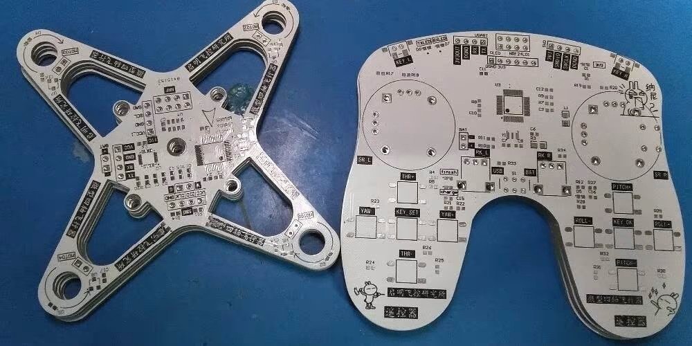
In today’s era of aerospace engineering, airplanes and spacecraft are equipped with flight control systems that play an imp role in helping pilots operate the aircraft safely and accurately. However, constructing these systems is challenging because they require numerous components to function seamlessly together. A really important part of making these systems is designing the hardware and the Printed Circuit Board (PCB), which is like the brain of the system. Now, let’s see a little bit about Kicad!
KiCAD is a set of tools that helps engineers design these flight control systems. It’s free and has everything needed to draw up the plans, arrange the parts on the circuit board and even test how it all works together.
This article will talk about how flight control systems are designed, focusing on the hardware and PCB parts using KiCAD. We’ll talk about the key parts, what to consider when designing them and the best methods to do it. We’ll also talk about why KiCAD is so great and how it helps engineers make the design process smoother.
Understanding Flight Control Systems
Flight control systems are important for keeping airplanes flying smoothly and on the right path. They’re made up of three main parts:
- Sensors: These gadgets gather data about the plane’s position, height, speed and other important stuff. They use things like gyroscopes, accelerometers and GPS.
- Control Computers: These are like the brains of the operation. They take the data from the sensors and figure out what the plane needs to do to stay on course. They’re usually small computers that are really good at making quick decisions.
- Actuators: These are the muscles of the system. They take the commands from the control computers and move the parts of the plane, like the wings or tail, to make sure it flies correctly.
Hardware Design Consideration
When making the hardware for a flight control system, there are a bunch of things to think about:
- Sensor Integration: Getting the sensors to work just right is super important for getting accurate info about the plane. This means putting them in the right spots, protecting them from interference, and making sure they talk well with the control computer.
- Microcontroller Choice: The microcontroller is like the brain of the system. Picking the right one means thinking about how powerful it needs to be, how much memory it needs, and what other gadgets it can connect to. Some common ones are ARM Cortex-M series and Atmel AVR microcontrollers.
- Power Management: Keeping things running smoothly without wasting power is key, especially for planes that run on batteries. This involves thinking about how much power everything uses, making sure the voltage is steady, and distributing power evenly to all the parts.
- Dealing with Tough Conditions: Flight control systems have to work in all kinds of rough situations, like extreme temperatures and vibrations. Designing the hardware means finding ways to handle these challenges, like keeping things cool, cushioning against bumps, and protecting against interference from other electronics.
- Safety Features: Making sure the system doesn’t fail catastrophically is crucial. This means building in backup systems, timers that watch for problems, and ways for the system to stay in control even if something goes wrong with one part.
PCB Design Using KiCAD

KiCAD is a really helpful tool for designing the circuit boards used in flight control systems. Here’s how it helps:
Drawing Schematics: With KiCAD’s Eeschema, engineers can create diagrams showing how all the parts connect together. They can organize these diagrams in a neat way, assign physical shapes to components, and check for any electrical mistakes.
Making the PCB Layout: KiCAD’s Pcbnew tool turns those diagrams into actual circuit board layouts. It makes things easier by automatically figuring out where to put the tracks that connect the components. Plus, it can handle special design rules to make sure everything can be made properly.
Component Library: KiCAD comes with lots of different parts ready to use, and engineers can even create their own if they need something special. This makes sure everything fits together correctly in the design.
Testing Before Making: Engineers can use KiCAD to simulate how the circuit will work before actually making it. This helps catch any problems early on and makes sure everything works as expected.
Seeing in 3D: KiCAD lets engineers see how the circuit board will look in 3D, which helps with fitting it into the aircraft properly.
Getting Ready for Production: Once everything looks good, KiCAD helps prepare the design files needed to actually make the circuit boards. This makes it easy to work with manufacturers to get everything built.
Design Workflow and Best Practices
When designing flight control systems using KiCad, it is essential to follow a structured workflow and adhere to best practices to ensure a successful outcome.
1. Requirements Gathering and Planning
The first step in the design process is to clearly define the system requirements. This includes performance specifications, environmental conditions, and safety standards. It is important to develop a comprehensive design plan that outlines the hardware architecture, component selection, and design constraints.
2. Schematic Capture and Component Selection
Once the requirements are defined, the next step is to create detailed schematics in KiCad’s Eeschema. Carefully select components that meet the design requirements and ensure proper component footprint assignment. Perform electrical rule checks to validate the schematic.
3. PCB Layout and Routing
After the schematic capture, the design needs to be translated into a physical PCB layout using KiCad’s Pcbnew. Follow best practices for component placement, routing, and signal integrity. Utilize KiCad’s design rule checks and constraint management tools to ensure manufacturability.
4. Simulation and Verification
Leverage KiCad’s simulation capabilities to verify the design before prototyping. Perform circuit simulations, signal integrity analysis, and electromagnetic compatibility (EMC) analysis to identify and address potential issues.
5. Prototyping and Testing
Once the design is verified through simulation, create prototypes for thorough testing and validation. Test the flight control system in relevant environmental conditions and perform functional tests to ensure compliance with system requirements.
6. Iteration and Refinement
Based on the test results, iterate and refine the design as necessary. Update the schematics, PCB layout, and simulations to incorporate improvements and address any identified issues.
7. Manufacturing and Integration
When the design is finalized, generate the necessary manufacturing output files (e.g., Gerber files, drill files) and engage with PCB fabrication and assembly services. Ensure proper integration of the PCB into the aircraft’s structure and system.
8. Documentation and Version Control
Maintain comprehensive documentation throughout the design process, including design specifications, test reports, and assembly instructions. Implement version control practices to track changes and facilitate collaboration within the engineering team.
Advantages of Using KiCad for Flight Control System Design
Choosing KiCad for flight control system design offers several advantages:
- Open-Source and Cost-Effective: As an open-source EDA suite, KiCad provides a cost-effective solution for hardware and PCB design, making it accessible to organizations of various sizes and budgets.
- Cross-Platform Compatibility: KiCad is available for multiple operating systems, including Windows, macOS, and Linux, ensuring flexibility and compatibility across different development environments.
- Community Support and Resources: KiCad has a large and active community of users and developers, providing access to extensive documentation, tutorials, and support forums. This facilitates knowledge sharing and problem-solving.
- Customizability and Extensibility: KiCad’s modular architecture and scripting capabilities allow for customization and integration with third-party tools. This enables engineers to tailor the design environment to their specific needs.
- Comprehensive Feature Set: KiCad offers a wide range of features, including schematic capture, PCB layout, simulation, and manufacturing output. This provides a complete solution for flight control system design.
- Interoperability and Data Exchange: KiCad supports various file formats for data exchange, enabling seamless collaboration with other EDA tools and integration into existing design workflows.
The above article is reference from – https://www.raypcb.com/flight-control-system-design/
Conclusion
In conclusion, KiCAD is a fantastic tool for making flight control systems easier to design. It’s free, easy to use and lots of people can help if you get stuck. Using KiCAD makes designing these systems simpler, which means airplanes can fly safer and better in today’s world.


