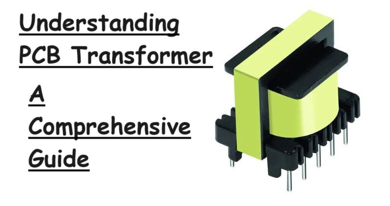
Understanding PCB Transformer: A Comprehensive Guide
Printed Circuit Board (PCB) transformers are essential components in modern electronic circuits, facilitating the transfer of electrical energy between different circuits through electromagnetic induction. This article delves into what PCB transformers are, their types, functionality, core materials and the key considerations for selecting the right PCB transformer. Let’s see the definition of what exactly is PCB Transformer!
What is a PCB Transformer?
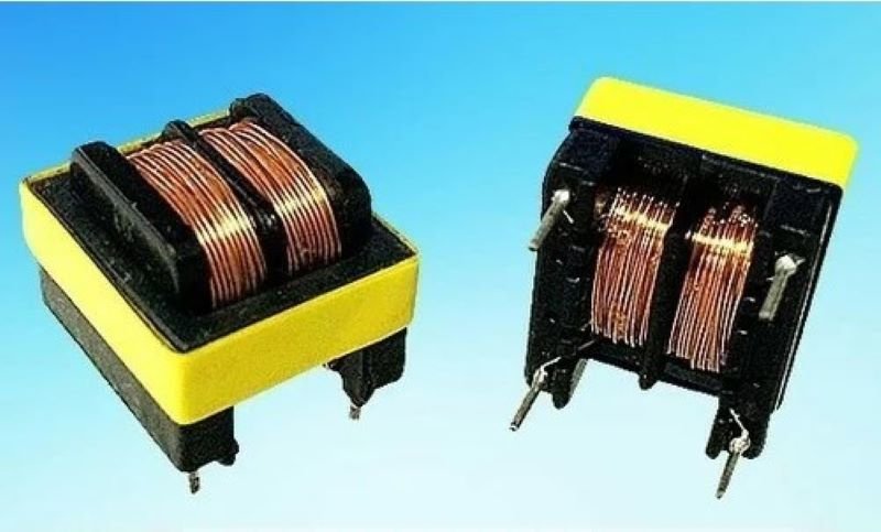
A PCB transformer is a compact transformer mounted directly onto a printed circuit board. Its primary function is to isolate electrical circuits and transform voltages from one level to another, ensuring the safe and efficient operation of electronic devices. PCB transformers are integral in various applications, including power supplies, signal processing, and audio equipment.
Types of PCB Transformers
PCB transformers come in various types, each designed to meet specific application needs:
- Step-Down Transformers: These reduce high voltage to a lower voltage suitable for the device’s operation.
- Step-Up Transformers: These increase lower voltage to a higher voltage required by certain components.
- Isolation Transformers: These provide electrical isolation between two circuits, enhancing safety and reducing noise.
- Autotransformers: These have a single winding that acts as both the primary and secondary winding, providing voltage transformation without isolation.
- Signal Transformers: Designed for signal processing applications, these transformers ensure the integrity and quality of transmitted signals.
How Do PCB Transformers Work?
PCB transformers operate on the principle of electromagnetic induction. They consist of primary and secondary windings wrapped around a magnetic core. When an alternating current (AC) flows through the primary winding, it creates a varying magnetic field, inducing a corresponding AC voltage in the secondary winding. The voltage induced in the secondary winding depends on the turns ratio between the primary and secondary windings.
The turns ratio determines whether the transformer steps up or steps down the voltage. For instance, a transformer with more turns on the primary winding than the secondary will step down the voltage, while the reverse configuration will step it up.
The Material for the Core of PCB Transformers
The core material of a PCB transformer significantly impacts its performance. Common core materials include:
- Ferrite: Known for high permeability and low core losses, ferrite cores are ideal for high-frequency applications.
- Laminated Steel: Suitable for low-frequency applications, laminated steel cores reduce eddy current losses.
- Powdered Iron: These cores offer good magnetic properties and are used in a variety of applications.
- Nanocrystalline and Amorphous Materials: These advanced materials provide excellent efficiency and performance in high-power applications.
Commutator and Interrupter Types of PCB Transformers
In the context of PCB transformers, commutators and interrupters refer to devices that manage the direction and interruption of current flow:
- Commutator Transformers: These transformers integrate a commutator, a rotary switch that periodically reverses the direction of current flow in the windings, used in applications requiring precise current direction control.
- Interrupter Transformers: These include an interrupter mechanism that periodically breaks the current flow, commonly used in applications where timing and control of current interruption are crucial.
How to Select the Right PCB Transformer?
Selecting the right PCB transformer involves considering several factors:
- Voltage and Current Ratings: Ensure the transformer can handle the required input and output voltages and currents.
- Turns Ratio: Choose based on whether you need a step-up, step-down, or isolation function.
- Frequency Range: Match the transformer’s core material and design to the operating frequency of your application.
- Size and Footprint: Ensure the transformer’s physical dimensions fit the available PCB space.
- Thermal Performance: Consider the thermal characteristics to prevent overheating.
- Regulatory Compliance: Ensure the transformer meets relevant safety and performance standards.
Summary
In Summary, PCB transformers are vital components in modern electronics, providing voltage transformation and electrical isolation. Understanding the types of PCB transformers, their working principles, core materials, and the specific roles of commutators and interrupters can help in selecting the appropriate transformer for your application. By considering voltage ratings, turns ratio, frequency range, size, thermal performance, and regulatory compliance, you can ensure optimal performance and reliability of your electronic circuits.