Arduino-Powered Robot Car Controlled via Smartphone Bluetooth
Robotics projects that you can do yourself have become really popular lately. They’re fun activities that appeal to all kinds of people, from enthusiasts to students to hobbyists. These projects let you get hands-on, combining electronics, coding, and building stuff. One project that’s especially cool is making a robot car that you can control with your phone using Bluetooth and Arduino. It’s a great choice for beginners who are just starting to learn about embedded technology.
Introduction
In today’s world of technology robotics projects are super fascinating. They give us a sneak peek into what the future might look like showing us how robots could be used in lots of different ways. Whether it’s robots fighting fires or keeping an eye on things with drones the options are endless. That’s why we decided to make a Bluetooth-controlled robot car using Arduino. It’s a project that combines wireless communication robotics and electronics in a really cool way.
Components required to build Wireless Robot Car
Before delving into the intricacies of the project, let’s outline the components needed for assembly:
- Arduino UNO
- L298N 2A Motor driver Module
- HC-05 Bluetooth Module
- 5v Geared Motors (2)
- Power Supply
- Robot Chassis
- Connecting Wires
- Controller App and Smartphone
L298N Motor Driver Pinout
The L298N Motor Driver is like a control center for the motors in your robot. It helps to manage how fast they go and in what direction. Here’s what each pin does:
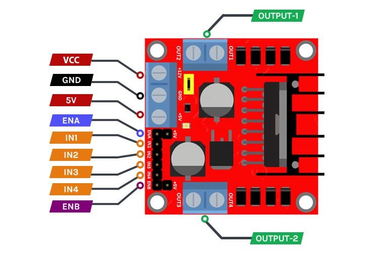
- VCC: This pin provides power to the board. It needs a voltage between 4 and 46 volts to work.
- GND: This pin connects the board to the ground to make sure everything works smoothly.
- 5V: It gives a constant 5 volts to power up the board’s internal circuits and other devices.
- ENA & ENB: These pins help control how fast the motors spin. If you set them to high, the motors will go at full speed, and low will stop them. You can also use Pulse Width Modulation (PWM) to control speed more precisely.
- IN1 & IN2: These pins decide which way the motors spin. Setting them high-low or low-high changes the direction, and setting them both low stops the motor.
- OUT-1 & OUT-2: These pins connect to the motors themselves. You can use them to power motors ranging from 5 to 35 volts.
Understanding these pins helps you manage your robot’s movement better and make it go where you want it to.
Chassis Assembly of Robot Car
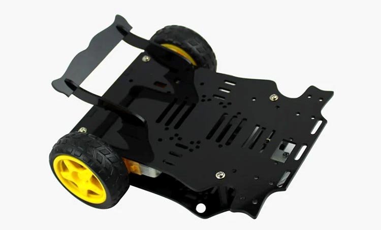
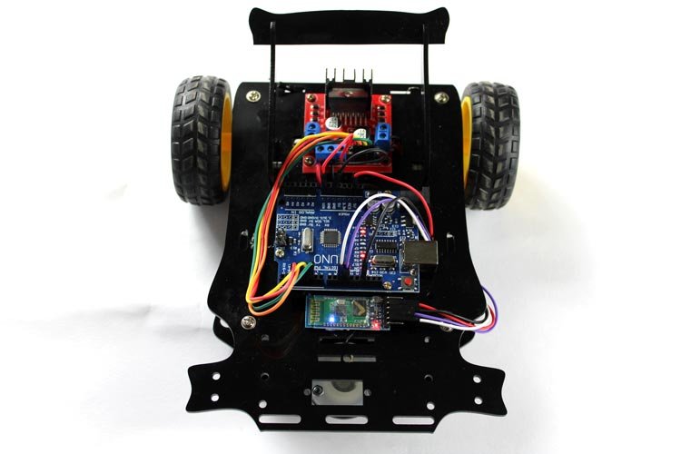
We’ve utilized an acrylic sheet cut with precision using laser technology, complete with all compatible fittings in place. Each component has been allotted its designated space, facilitating easy fitting with standard screwdrivers. For similar chassis prototypes, you can explore various online platforms.
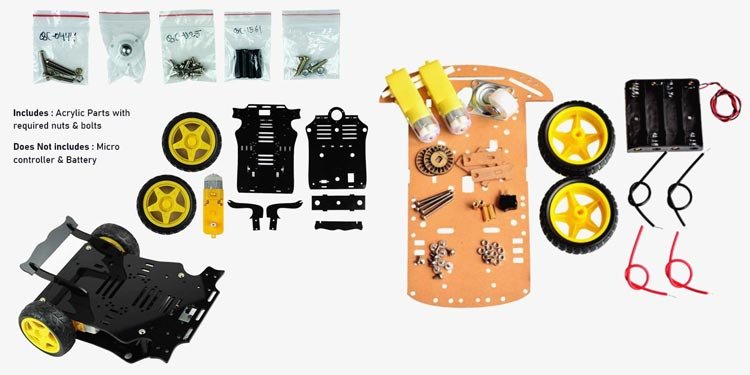
These kits include essential components such as motors, battery holders, wheels, and screws. Assembly simply involves selecting the parts and securely screwing them into place. Manufacturer assembly videos are also available for reference. These kits are not only cost-effective but also boast high durability, with precise fittings ensuring worry-free assembly. Take a look at my chassis prototype post-fitting.
Arduino Bluetooth Controlled Robot Circuit Diagram
Here is the detailed circuit diagram for the Bluetooth-controlled Robot Car. The design is straightforward, making it easy to comprehend and replicate.
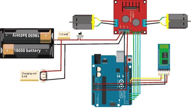
Let’s examine the connections:
To begin, establish a connection between the Bluetooth HC-05 module and the Arduino board. Verify data reception by monitoring the serial monitor in the IDE. In my setup, the Txd and Rxd pins of the HC-05 module are connected to digital pins 11 and 10, respectively. The Bluetooth module is powered by the Arduino, with its power pins connected to the corresponding Arduino power pins.
The Arduino itself receives power from the L298N motor driver board via the 5V output terminal and ground.
Now, regarding the connections for the L298N:
Since we’ve already reviewed the pinouts for the L298N motor driver, interfacing it with the Arduino is straightforward.
By connecting the positive terminal of the battery to the VCC of the driver board, we can power our motor driver. We’re using a 2S lithium-ion battery with an output voltage of around 7.4 volts. This choice is based on the utilization of BO-geared motors, which operate within a voltage range of 3 to 12 volts. Despite a decrease of approximately 2 volts at the motor’s output terminal due to internal circuitry, the impact on the motor’s functionality is minimal. Consequently, the motors will receive approximately 5.5 to 6 volts.
To link the digital direction control pins to the Arduino, connect any four digital pins of the Arduino to the IN1, IN2, IN3, and IN4 pins of the driver board. Adjust the code accordingly to correspond to the correct Arduino pins.
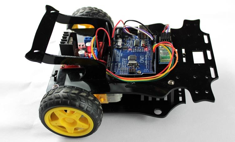
The actual connections and operations are as described above.
App Configuration to interface Bot with Smartphone
Connecting a robot car to your smartphone is a straightforward task. Simply download an application from the Play Store called “Bluetooth RC Car”. This app comes with a preconfigured interface designed to control various types of Bluetooth RC robots. It features graphical buttons, sliders, and even sensors like accelerometers for intuitive control. Additionally, it includes built-in functionalities for controlling different features such as toggling the front and rear lights of the car.
To get started, head to the Play Store on your Android smartphone and search for “Bluetooth RC Car”. You’ll find an app that resembles the following:
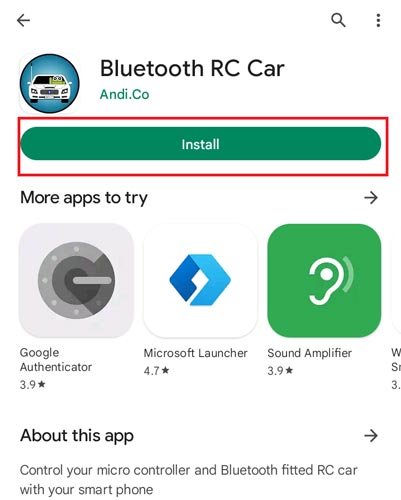
- Install the app and launch it. You’ll be greeted by an attractive interface designed for easy car control.
Working of Robot Car- Controlled by Smartphone
As we understand, the Arduino acts as the central processing unit of the robot car. Programmed through the Arduino IDE (Integrated Development Environment), it receives and processes commands sent via Bluetooth. The programming code interprets these signals and translates them into specific actions for the motors, such as moving forward, backward, turning left or right, and stopping.
Before proceeding, ensure the robot car’s switch is turned ON and verify that the batteries are fully charged. Thoroughly inspect all connections to ensure they are secure and not loose.
The wireless communication between the robot and the smartphone is enabled by the Bluetooth connectivity feature, utilizing the HC-05 module.
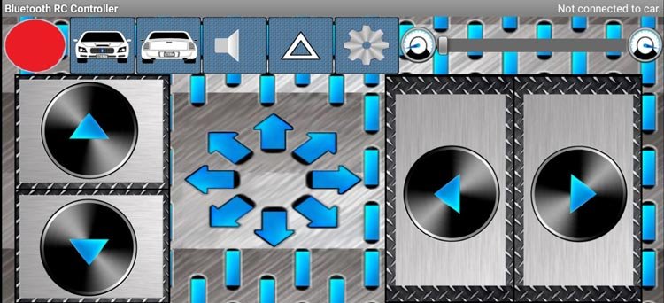
On the Bluetooth-enabled smartphone, the mobile app provides a control interface. This interface enables the user to send commands to the robot car, specifying desired actions or movements.
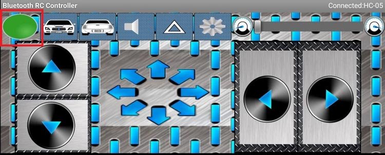
Next, upload the code to the Arduino and verify the blinking LEDs of the Bluetooth module. Then, open the application, activate the smartphone’s Bluetooth, and pair the app with the Bluetooth module named “HC-05”. Upon successful pairing, the red indicator at the top left corner of the application interface will change to green.
Once the connection is established and the control interface is ready, users can wirelessly operate the robot car using their smartphone. Control signals are transmitted via Bluetooth, received by the Arduino board, which interprets them and regulates the motors accordingly, executing the desired movements.
Arduino Code for Bluetooth-Controlled Robot Car
The Bluetooth module utilizes Serial Communication to transmit data. The program reads data from the Bluetooth module available on the serial port. Based on the received commands or data, the processor executes the desired movement function.
To facilitate communication with the Bluetooth module, we’ve incorporated the SoftwareSerial Library. Within the code, Pin 11 is designated as RX, which should be connected to the TxD of the Bluetooth module. Similarly, pin 10 is assigned to the RxD of the Bluetooth module. Additionally, we’ve defined the digital pins 2, 3, 4, and 5 of the Arduino as IN1, IN2, IN3, and IN4 pins, respectively.
#include<SoftwareSerial.h>
#define IN1 2
#define IN2 3
#define IN3 4
#define IN4 5
//#define EN1 6
//#define EN2 5
SoftwareSerial bt(11, 10); // RX, TX
char data;
In the setup() function, we initiate hardware serial communication at a baud rate of 9600. Additionally, the bt.begin() function initializes Bluetooth communication at the same baud rate. Furthermore, we set the Pinmodes and initially set all direction control pins to LOW to prevent any motor movement.
void setup() {
  Serial.begin(9600);
  pinMode(IN1, OUTPUT);
  pinMode(IN2, OUTPUT);
  pinMode(IN3, OUTPUT);
  pinMode(IN4, OUTPUT);
  //pinMode(EN1, OUTPUT);
  //pinMode(EN2, OUTPUT);
  digitalWrite(IN1, LOW);
  digitalWrite(IN2, LOW);
  digitalWrite(IN3, LOW);
  digitalWrite(IN4, LOW);
  //analogWrite(EN1,63);
  //analogWrite(EN2,63);
  bt.begin(9600);
}
Within the Loop() function, we continuously monitor the data available on the serial port and display it on the Serial Monitor to verify the functionality of the Bluetooth module. You can test this by sending any character command from your smartphone, connected to the terminal.
We evaluate the received data using Switch Case statements, and if a condition is met, the corresponding statement is executed.
We’ve defined five distinct movement functions outside the loop, each of which is called within its respective switch statement.
void loop() {
   while (bt.available())   {
      { data = bt.read();
        Serial.println(data);}
      switch (data)
       {
          case 'F':
            //Serial.println("Forward");
            forward();
            break;
          case 'B':
           //Serial.println("Reverse");
            reverse();
            break;
          case 'L':
           //Serial.println("Left");
            left();
            break;
          case 'R':
            //Serial.println("Right");
            right();
            break;
          case 'S':
            //Serial.println("Stop");
            stoprobot();
            break;
          }
      }
       if (bt.available() < 0)
        {
         //Serial.println("No Bluetooth Data ");
        }
  delay(100);
}
Movement Functions: We’ve established four distinct movement functions alongside a Stop function. These functions manipulate the four digital pins (IN1, IN2, IN3, IN4) to govern all directional movements. Utilizing combinations of HIGH and LOW commands, we control the spinning of the wheels. Occasionally, developers may need to tweak these commands to align with their hardware connections and ensure proper directionality.
void forward() {
  digitalWrite(IN1, HIGH);
  digitalWrite(IN2, LOW);
  digitalWrite(IN3, LOW);
  digitalWrite(IN4, HIGH);
  delay(20);
}
void reverse() {
  digitalWrite(IN1, LOW);
  digitalWrite(IN2, HIGH);
  digitalWrite(IN3, HIGH);
  digitalWrite(IN4, LOW);
  delay(20);
}
void left() {
  digitalWrite(IN1, HIGH);
  digitalWrite(IN2, LOW);
  digitalWrite(IN3, HIGH);
  digitalWrite(IN4, LOW);
  delay(20);
}
void right() {
  digitalWrite(IN1, LOW);
  digitalWrite(IN2, HIGH);
  digitalWrite(IN3, LOW);
  digitalWrite(IN4, HIGH);
  delay(20);
}
void stoprobot() {
  digitalWrite(IN1, LOW);
  digitalWrite(IN2, LOW);
  digitalWrite(IN3, LOW);
  digitalWrite(IN4, LOW);
  delay(20);
}
I hope you found the project enjoyable and gained some valuable insights from it. If you have any questions or need further clarification, feel free to leave them in the comment section below. I’m here to help!
Code
#include <SoftwareSerial.h>

#define IN1 2
#define IN2 3
#define IN3 4
#define IN4 5

SoftwareSerial bt(11, 10); // RX, TX
char data;

void setup() {
  Serial.begin(9600);
  pinMode(IN1, OUTPUT);
  pinMode(IN2, OUTPUT);
  pinMode(IN3, OUTPUT);
  pinMode(IN4, OUTPUT);
  digitalWrite(IN1, LOW);
  digitalWrite(IN2, LOW);
  digitalWrite(IN3, LOW);
  digitalWrite(IN4, LOW);
  bt.begin(9600);
}

void loop() {
  while (bt.available()) {
    data = bt.read();
    Serial.println(data);
    switch (data) {
      case 'F':
        forward();
        break;
      case 'B':
        reverse();
        break;
      case 'L':
        left();
        break;
      case 'R':
        right();
        break;
      case 'S':
        stoprobot();
        break;
    }
  }
  delay(100);
}

void forward() {
  digitalWrite(IN1, HIGH);
  digitalWrite(IN2, LOW);
  digitalWrite(IN3, LOW);
  digitalWrite(IN4, HIGH);
  delay(20);
}

void reverse() {
  digitalWrite(IN1, LOW);
  digitalWrite(IN2, HIGH);
  digitalWrite(IN3, HIGH);
  digitalWrite(IN4, LOW);
  delay(20);
}

void left() {
  digitalWrite(IN1, HIGH);
  digitalWrite(IN2, LOW);
  digitalWrite(IN3, HIGH);
  digitalWrite(IN4, LOW);
  delay(20);
}

void right() {
  digitalWrite(IN1, LOW);
  digitalWrite(IN2, HIGH);
  digitalWrite(IN3, LOW);
  digitalWrite(IN4, HIGH);
  delay(20);
}

void stoprobot() {
  digitalWrite(IN1, LOW);
  digitalWrite(IN2, LOW);
  digitalWrite(IN3, LOW);
  digitalWrite(IN4, LOW);
  delay(20);
}
This code sets up a Bluetooth-controlled robot car. It defines movement functions for forward, reverse, left, right, and stop, which are executed based on the commands received over Bluetooth. Make sure to connect the Bluetooth module to pins 10 and 11 on the Arduino, and the motor driver’s control pins to pins 2, 3, 4, and 5. Adjust the delays and other parameters as needed for your specific setup.