Pinout Fundamentals: Understanding Definitions and Basics
What is a Pinout?
A pinout is a diagram or table that provides information about the connections and functions of the pins or terminals on a specific electronic device or component. It shows the arrangement of pins and their corresponding functions, allowing users to understand how to connect and interact with the device.
Pinouts are commonly used in the field of electronics, especially when dealing with devices such as connectors, cables, integrated circuits, and other electronic components. They serve as a reference guide for technicians, engineers, and hobbyists, helping them correctly identify and connect the various pins or terminals of a device.
Components of a Pinout
A typical pinout consists of the following components:
- Pin Number: Each pin on a component is assigned a unique number for identification purposes. These numbers are usually displayed in sequential order.
- Pin Name: The pin name describes the function or purpose of the pin. It helps users understand the role of each pin in the overall circuit.
- Pin Description: The pin description provides additional details about the pin, such as its voltage, current, or signal type.
- Pin Connection: This section illustrates how the pin is connected to other components or devices. It may include information about the pin’s input or output characteristics.
How to Read a Pinout?
Now that you have a basic understanding of what a pinout is, let’s dive into the process of reading one:
- Identify the Pinout: Locate the pinout diagram or table for the specific component you are working with. This information can usually be found in the datasheet or technical manual provided by the manufacturer.
- Study the Pin Configuration: Take a closer look at the pin numbers and their corresponding names. Familiarize yourself with the overall layout of the pinout.
- Understand the Pin Functions: Read the pin descriptions to gain a clear understanding of the purpose of each pin. This will help you determine how the component interacts with other devices in the circuit.
- Analyze the Pin Connections: Examine the pin connections to identify how the component is connected to other components or devices. Pay attention to input and output pins, as well as any special features or requirements.
- Refer to the Datasheet: If you come across any unfamiliar terms or symbols in the pinout, refer to the datasheet for further clarification. The datasheet will provide detailed information about the component’s specifications and usage.
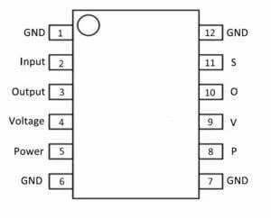
In the provided diagram, you’ll begin with the initial column, which denotes the “ground” link. Trace along this row until you reach the “GND” connection. Moving to the second column from the left, you’ll find the “input” connection, succeeded by “S” representing “signal.” Progressing to the third column, you’ll encounter the “output” connection, followed by “O” indicating “output.” The fourth column designates the “voltage reference” connection, marked with “V” for “voltage.” Continuing to the fifth column, you’ll find the “power” connection, denoted by “P” for “power.” Finally, in the sixth column, you’ll spot the “ground” connection once again, signified by “GND” for “ground.”
Tips for Reading Pinouts
Here are some additional tips to help you read pinouts effectively:
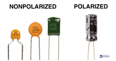
- Pay Attention to Pin Types: Pins can have different types, such as power pins, ground pins, input pins, output pins, or communication pins. Understanding the purpose of each pin type will give you a better understanding of the component’s functionality.
- Use Color Codes: Some pinouts may include color codes to indicate different pin functions. These color codes can be helpful in quickly identifying the purpose of each pin.
- Double-Check Pin Numbers: Ensure that you are referring to the correct pin numbers when connecting components. Mistakenly connecting pins can lead to circuit malfunctions or damage to the components.
- Consult Online Resources: If you’re having trouble understanding a specific pinout or need additional information, there are numerous online resources, forums, and communities dedicated to electronics that can provide guidance.
Practical Examples of Pinout
Let’s take a look at some practical examples of pinouts:
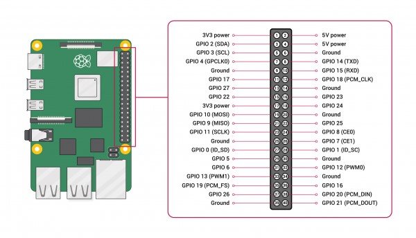
1. Raspberry Pi GPIO Pinout
The Raspberry Pi is a popular single-board computer used for a wide range of projects. The GPIO (General Purpose Input/Output) pinout provides information about the pins on the Raspberry Pi board that can be used for digital input/output, analog input, and other functionalities.
Here’s an example of a Raspberry Pi GPIO pinout:
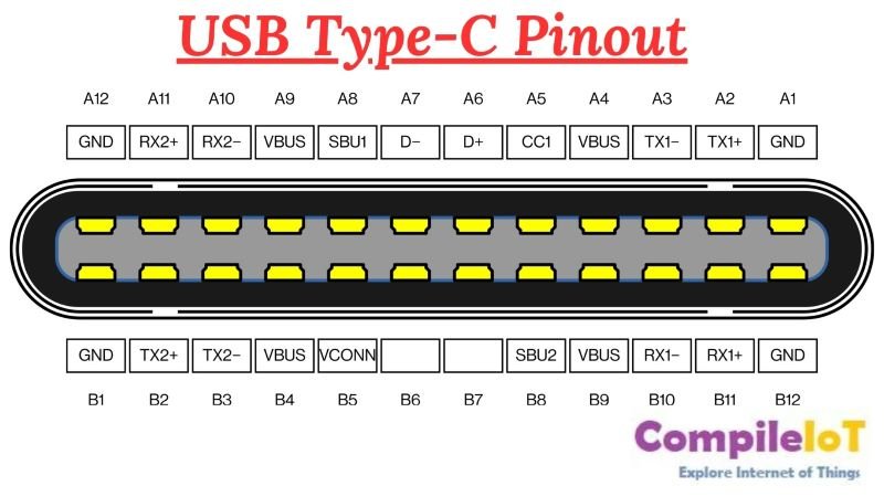
2. USB Type-C Pinout
USB Type-C is a versatile connector used for various devices, including smartphones, laptops, and tablets. The USB Type-C pinout diagram shows the pin assignments for power, data transfer, and other functionalities.
Here’s an example of a USB Type-C pinout:
3. Arduino Nano Pinout
The Arduino Nano is a compact and popular Arduino board. The Arduino Nano pinout diagram provides information about the pins on the board, including power, digital input/output, analog input, PWM, and other essential connections.
4. RS-232 Pinout
The RS-232 pinout consists of a set of pins that are used to transmit and receive data, as well as control signals. The standard defines a 25-pin connector, but a more common variation is the 9-pin connector, which is often used in modern devices.
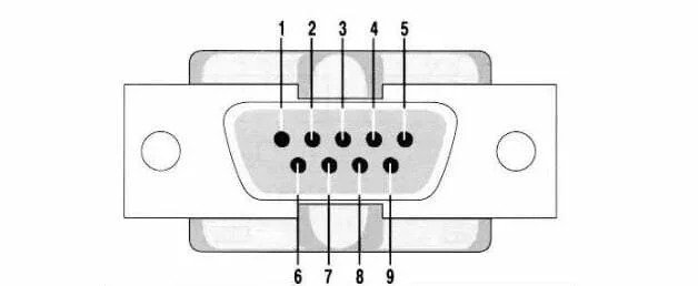
Pin number and signal:
- Data carrier detect
- Received data
- Transmitted data
- Data terminal ready
- Signal ground
- Data set ready
- Request to send
- Clear to send
- Ring indicator
Conclusion
Learning to read a pinout might seem tricky at first, but don’t worry! With practice and understanding, it gets easier. Just follow the steps in this guide and get familiar with the layout, what each pin does, and how they connect. Soon enough, you’ll be confidently using pinouts for your electronic projects.
Remember, always refer to the manufacturer’s datasheet for accurate and detailed information about the pinout of a specific component.