How to Build a NAND Gate with Transistor
In this article, we will guide you through the process of building a NAND gate using transistors. A NAND gate is a fundamental building block in digital electronics, and understanding how to construct one can be a great way to deepen your understanding of circuit design.
What is a NAND logic Gate?
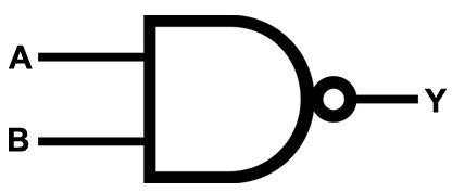
A NAND gate is a digital logic gate that produces an output of “0” only when all of its inputs are “1.” In other words, it performs the logical AND operation on two or more inputs and then negates the result. The symbol for a NAND gate is represented by an AND gate followed by a small circle at its output, indicating the negation.
NAND Gate Symbol
Truth table of NAND Logic Gate
| Input A | Input B | Output |
|---|---|---|
| 0 | 0 | 1 |
| 0 | 1 | 1 |
| 1 | 0 | 1 |
| 1 | 1 | 0 |
As seen from the truth table, the output of a NAND gate is “1” for all combinations of inputs except when both inputs are “1.” When both inputs are “1,” the output of the NAND gate becomes “0.”
Components Needed for building NAND gate
Building a NAND gate requires a few basic electronic components. Here is a list of the components you will need:
- Resistors: You will need two resistors, typically in the range of 220-10k ohms. These resistors are used to limit the current flowing through the gate.
- Transistors: You will need two NPN transistors, such as the commonly used 2N3904. Transistors act as switches in digital circuits.
- Diodes: Two diodes, such as 1N4148, are required to protect the transistors from reverse voltage.
- Power Supply: You will need a power supply to provide the necessary voltage for the circuit. A 5V power supply is commonly used.
- Breadboard: A breadboard is a convenient platform for prototyping circuits. It allows you to easily connect and disconnect components without soldering.
- Jumper Wires: Jumper wires are used to make connections between the components on the breadboard.
Circuit Diagram of NAND Gate using Transistors
The diagram presented depicts a NAND gate utilizing five NPN transistors. In this configuration, I1 and I2 denote the input signals, while O1 signifies the output.
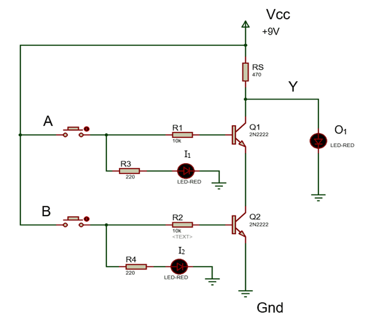
To construct a NAND gate employing only two NPN transistors, commence by linking the collector of the first NPN transistor (Q1) to Vcc (positive voltage) via a resistor (RS). This action establishes the power connection for Q1. Proceed by connecting the emitter of Q1 to the collector of the second NPN transistor (Q2), thereby establishing a crucial linkage between the two transistors, forming the core of our NAND gate. The collector of Q1 should then be connected to the output terminal Y, which serves as the output for our NAND gate.
Subsequently, affix a resistor (R1) between the base of Q1 and the input terminal A. This resistor serves to restrict the current flowing into the base of Q1. Similarly, attach a resistor (R2) between the base of Q2 and input terminal B, effectively controlling the current entering the base of Q2.
The construction of a simple 2-input NAND gate utilizing RTL Resistor-transistor switches involves connecting them together as depicted in the aforementioned circuit, with the inputs directly linked to the transistor bases. In this setup, either transistor must be in the cut-off state “OFF” to yield an output at Y and turn on the LED.
A NAND gate circuit closely resembles an AND gate circuit, with the primary distinction being that the output is obtained from the collector of the first transistor instead of being connected to the emitter of the second transistor.
When both inputs are set to HIGH, both transistors conduct through their collector-emitter paths, effectively creating a short circuit to ground. This diversion of current away from the output leads to a LOW output state.
Conversely, if either transistor turns off, the supply current is unable to flow through the transistors to the ground. Instead, it traverses through the output circuit (LED), resulting in a HIGH output. Thus, the output will be HIGH if either one of the inputs is LOW.
Building the NAND Gate
Now that you have gathered all the necessary components, let’s proceed with building the NAND gate:
- Start by placing the two transistors on the breadboard. Make sure the flat side of the transistor faces towards you, and leave some space between them.
- Connect the emitter of the first transistor to the ground rail of the breadboard using a jumper wire.
- Connect the collector of the first transistor to the base of the second transistor using another jumper wire.
- Connect the emitter of the second transistor to the ground rail of the breadboard.
- Connect the collector of the second transistor to the positive rail of the breadboard using a jumper wire.
- Place a resistor between the base of the first transistor and the input terminal of the NAND gate.
- Connect the anode of the first diode to the base of the first transistor, and the cathode to the positive rail of the breadboard.
- Connect the anode of the second diode to the base of the second transistor, and the cathode to the positive rail of the breadboard.
- Connect the output terminal of the NAND gate to an LED, and connect the other terminal of the LED to the positive rail of the breadboard.
- Connect a current-limiting resistor to the LED, and connect the other end of the resistor to the ground rail of the breadboard.
- Finally, connect the power supply to the positive and ground rails of the breadboard.
Testing the NAND Gate
Once you have finished building the NAND gate, it’s time to test its functionality. Follow these steps:
- Apply a high voltage (5V) to one of the input terminals of the NAND gate.
- Apply a high voltage (5V) to the other input terminal of the NAND gate.
- Observe the output terminal of the NAND gate. It should be low (0V), indicating a logical “false” state.
- Now, apply a low voltage (0V) to one of the input terminals of the NAND gate.
- Observe the output terminal again. It should be high (5V), indicating a logical “true” state.
If the NAND gate functions as expected, congratulations! You have successfully built a NAND gate using basic electronic components. You can now experiment with different input combinations and observe the corresponding outputs.