What is the Meaning of Schematic Diagram?
A schematic diagram is a visual representation of an electrical circuit, showing how various components are connected and how electricity flows through the system. In this article, we will explore the basics of schematic diagrams, the standards for schematic symbols, the different types of schematic symbols, the values and attributes associated with them and finally, the difference between schematic and wiring diagrams.
What is a Schematic Diagram?
A schematic diagram is a simplified representation of an electrical circuit. It uses standardized symbols to depict the different components of the circuit and their connections. Schematic diagrams are used by electricians, engineers, and technicians to understand, troubleshoot, and design electrical systems.
Schematic diagrams are created using a set of standardized symbols that represent various electrical components such as resistors, capacitors, diodes, transistors, and more. These symbols are universally recognized and help ensure clear communication and understanding among professionals in the field.
Standards for schematic symbol
To ensure consistency and clarity in schematic diagrams, there are several standards that govern the use of schematic symbols. The most widely used standard is the International Electrotechnical Commission (IEC) 60617 standard, also known as the “Graphical Symbols for Diagrams” standard. This standard provides a comprehensive set of symbols for various electrical and electronic components.
Other standards, such as the American National Standards Institute (ANSI) Y32.2 standard and the Institute of Electrical and Electronics Engineers (IEEE) 315 standard, also provide guidelines for schematic symbols.
What are the different schematic symbols?
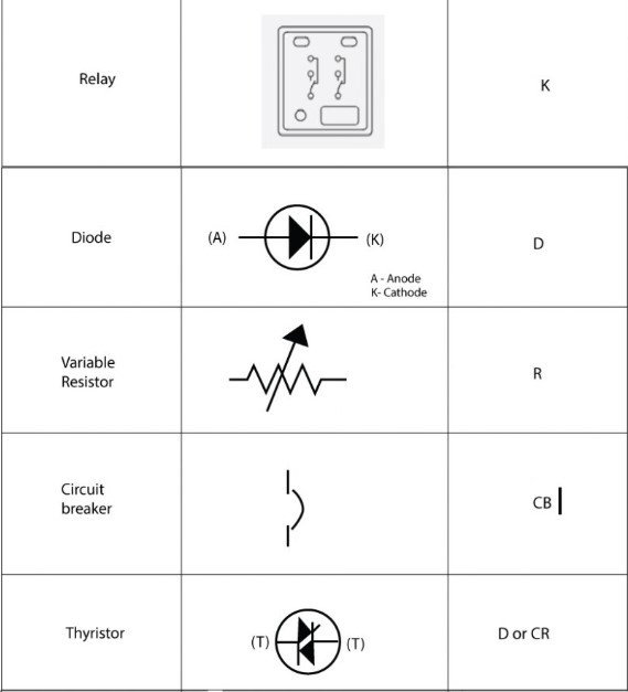
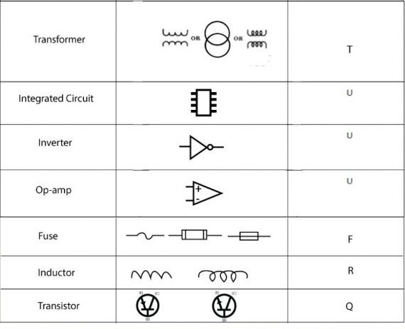
There are numerous schematic symbols used to represent different electrical components in a circuit. Here are some commonly used symbols:
- Resistor: The resistor symbol is represented by a zigzag line.
- Capacitor: The capacitor symbol consists of two parallel lines.
- Diode: The diode symbol is represented by an arrow pointing in one direction.
- Transistor: The transistor symbol can vary depending on the type of transistor (e.g., NPN or PNP).
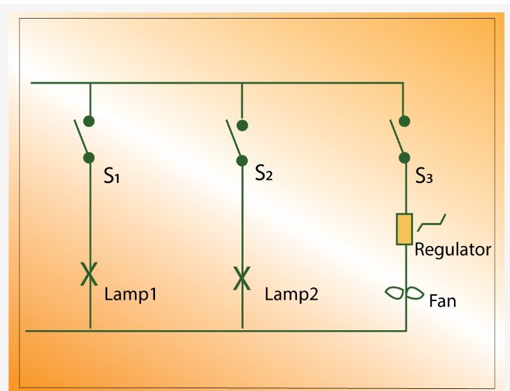
- Switch: The switch symbol is represented by a line with a gap.
- Inductor: The inductor symbol is represented by a coil or a series of loops.

These are just a few examples of the many schematic symbols used in electrical circuits. Each symbol represents a specific component and helps electricians and engineers understand how the circuit functions.
Values and attributes
In addition to the symbols themselves, schematic diagrams also include values and attributes associated with each component. These values provide important information about the specific characteristics of the component, such as resistance, capacitance, voltage ratings, and more.
For example, a resistor symbol may include a value indicating its resistance in ohms (Ω), while a capacitor symbol may include a value indicating its capacitance in farads (F). These values help professionals select the right components for a circuit and ensure its proper functioning.
The international system of units
In circuit diagrams, attribute values can range from minuscule to immense. To prevent cluttering diagrams with lengthy strings of zeros for values such as 1,000,000,000 or .0000000001, we adopt the International System of units (SI). The table below illustrates the SI units commonly employed in schematic diagrams.
| Prefix | Symbol | Value | Powers of 10 |
|---|---|---|---|
| Tera | T | 100000000000 | 1012 |
| Giga | G | 100000000 | 109 |
| Mega | M | 1000000 | 106 |
| Kilo | k | 1000 | 103 |
| Mili | m | 0.001 | 10-3 |
| Micro | u | 0.000 001 | 10-6 |
| Nano | n | 0.000 000 001 | 10-9 |
| Pico | p | 0.000 000 000 001 | 10-12 |
What is the difference between schematic and wiring diagram?
A schematic diagram focuses on the electrical circuit itself, showing the connections between components and how electricity flows through the system. It is a more abstract representation that helps professionals understand the overall structure and function of the circuit.
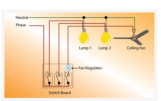
On the other hand, a wiring diagram provides a more detailed and practical view of the circuit. It shows the physical layout of the wires, connections, and components, making it easier to install, repair, or modify the electrical system.
Conclusion
In summary, schematic diagrams are essential tools in electrical engineering, offering a standardized visual representation of circuits. They use symbols and values to convey component connections and attributes, adhering to international standards for clarity. While schematic diagrams provide a conceptual understanding, wiring diagrams offer a practical layout for installation and maintenance. Together, they enable efficient troubleshooting and design in the field of electrical systems.