Series vs Parallel Circuit – What’s the difference?
In electrical circuits, there are two common configurations are series and parallel. These configurations play an imp role in determining how electricity flows through a circuit and how components are connected. Understanding the difference between series and parallel circuits is fundamental for anyone working with electronics or simply curious about how things work.
What is a Series Circuits?
A series circuit is a type of electrical circuit in which the components are arranged in a single pathway for the flow of electric current. In a series circuit, the same current passes through all the components, and the voltage is divided among the various elements. This means that if one component in the circuit fails, the entire circuit will be disrupted.
Understanding the characteristics and functioning of a series circuit is crucial for anyone interested in electrical engineering, electronics, or even basic household wiring.
Components of a Series Circuit
In a series circuit, the components are connected end to end, forming a single path for the current to flow. The basic components in a series circuit include:
- Power Source: This can be a battery or an electrical outlet supplying the voltage for the circuit.
- Load: The load is the device or devices that utilize the electrical energy, such as a light bulb, motor, or any other electrical appliance.
- Conductors: Wires or conductive pathways that connect the components and allow the flow of current.
- Switches: Optional components that can be used to control the flow of current in the circuit.
- Fuses or Circuit Breakers: Safety devices that protect the circuit from overcurrent or short circuits.
Characteristics of a Series Circuit
Several key characteristics define the behavior of a series circuit:
- Current: In a series circuit, the current remains constant throughout the circuit. This means that the same amount of current flows through all the components.
- Voltage: The total voltage in a series circuit is divided among the various components. Each component experiences a voltage drop, and the sum of the voltage drops across all components equals the total voltage supplied by the source.
- Resistance: The total resistance in a series circuit is the sum of the individual resistances of the components. As a result, adding more resistive components to the circuit increases the total resistance and reduces the overall current flow.
- Failure Impact: One of the critical aspects of a series circuit is that if one component fails or is removed, the entire circuit is interrupted, and all components cease to function. This characteristic is essential to consider in applications where reliability and redundancy are crucial.
What is a Parallel Circuits?
A parallel circuit is a type of electrical circuit in which the current flows through multiple paths. Unlike a series circuit where the current flows through a single path, in a parallel circuit, the current has the option to flow through different branches simultaneously. This means that if one component in a parallel circuit fails, the other components can continue to operate independently.
Components of a Parallel Circuit
In a parallel circuit, each component is connected across the same voltage source. This means that all the components in the circuit have the same voltage across them. The components are connected in such a way that there are multiple paths for the current to flow. If there are n components in a parallel circuit, each component will have its own branch through which the current can flow.
One of the key features of a parallel circuit is that the voltage across each component remains constant, while the current can vary. This is in contrast to a series circuit, where the current remains constant and the voltage can vary across different components.
Applications of Parallel Circuits
Parallel circuits are widely used in various electrical and electronic systems. Some common applications of parallel circuits include:
- Household Wiring: The electrical wiring in homes and buildings is typically set up as a parallel circuit. This allows for independent control of different electrical outlets and ensures that the failure of one outlet does not affect the others.
- Electronic Devices: Many electronic devices, such as computers, televisions, and audio systems, use parallel circuits to power multiple components independently.
- Lighting Systems: Lighting circuits often utilize parallel connections to power multiple light fixtures while allowing individual control and independent operation.
- Automotive Electrical Systems: The electrical systems in vehicles make use of parallel circuits to power various components, such as lights, sensors, and entertainment systems.
Solar Panel Series vs Parallel Circuit Configurations
When installing your solar panels, it’s crucial to consider how you link them together. There are primarily two methods for this: series connection and parallel connection. However, the dilemma arises: which option is superior? Let’s delve into this question.
Series Circuit Configuration
In a series circuit configuration, the solar panels are connected end-to-end, forming a single pathway for the flow of current. This means that the total voltage across the connected panels is additive, while the current remains constant throughout the circuit. In other words, the voltage output of each panel adds up to provide a higher total voltage output for the entire series.
Parallel Circuit Configuration
In a parallel circuit configuration, each solar panel is connected to the charge controller or inverter individually, creating multiple pathways for the flow of current. This means that the voltage across each panel remains constant, while the total current output is additive. In other words, the current output of each panel adds up to provide a higher total current output for the entire parallel circuit.
Series vs Parallel – Which One to Choose?
So, the big question remains – which circuit configuration is the best choice for your solar panel system? The answer depends on a variety of factors, including your specific energy needs, installation constraints, and shading considerations.
If you prioritize higher voltage output and have minimal shading or performance variations among your panels, a series circuit configuration may be the most suitable option for your system. On the other hand, if shading or panel-level performance variations are a concern, and you require higher current output, a parallel circuit configuration may be the better choice.
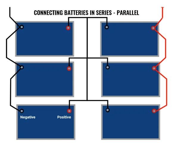
Batteries Connection in Series vs Parallel
Similar to solar panels, the configuration of batteries in a solar energy system can also be done in series or parallel. This decision can have significant implications for the overall performance and efficiency of the system.
When batteries are connected in series, the voltage of each battery adds up, while the overall current remains constant. This can be beneficial for applications that require higher voltage, such as off-grid systems or certain types of inverters. However, it’s important to ensure that the batteries are well-matched in terms of capacity and state of charge to prevent imbalances and potential damage to the batteries.
On the other hand, connecting batteries in parallel allows for the total voltage to remain constant while the overall current output is additive. This configuration can be advantageous for applications that require higher current output or for systems with varying energy demands. However, it’s crucial to use proper cabling and protection devices to ensure balanced charging and discharging of the batteries.
Tips for Series Circuit Wiring
Here are some tips to keep in mind when wiring batteries in a series circuit:
- Ensure that all batteries in the series have the same capacity and chemistry to prevent imbalances in charging and discharging.
- Be mindful of the total voltage output, as it will be the sum of the individual battery voltages in the series.
- Understand that the overall capacity of the battery bank will be equivalent to the capacity of a single battery in the series.
- Use caution when connecting and disconnecting series-wired batteries to avoid short circuits and potential damage to the batteries or connected devices.
Tips for Parallel Circuit Wiring
In a parallel circuit, the positive terminals of all batteries are connected together and the negative terminals are also connected together. This setup maintains the same voltage as a single battery but increases the overall capacity of the system. Here are some tips for wiring batteries in a parallel circuit:
- Ensure that all batteries in the parallel setup have the same voltage and chemistry to prevent imbalances in charging and discharging.
- Be aware that the overall voltage of the battery bank will be equivalent to the voltage of a single battery in the parallel setup.
- Understand that the total capacity of the battery bank will be the sum of the capacities of the individual batteries in the parallel setup.
- Take precautions to balance the load across all batteries in the parallel configuration to ensure even distribution of current.
Difference between Series and Parallel Circuits
Here are some common key differences between series and parallel circuits:
| Features | Series Cricuit | Parallel Circuits |
|---|---|---|
| Current Flow | The same current flows through each component. | Current divides and flows through each path. |
| Voltage Distribution | Voltage divides across each component. | Voltage across each component is the same. |
| Resistance/Impedance | Total resistance is the sum of individual resistances. | Total resistance is less than the smallest individual resistance. |
| Adding Components | Increases total resistance. | May decrease total resistance. |
| Failure of a Component | Causes the whole circuit to fail (open circuit). | Other components can still function. |
| Example | Old Christmas lights, some battery configurations. | Home wiring, electronic appliances. |
| Power Distribution | Not efficient for components with different power needs. | More efficient and consistent for each component. |
| Current Load Handling | Limited by the weakest component. | Better suited for high current loads. |