Opamp as differentiator (active differentiator)
An operational amplifier (op-amp) can be used to create an active differentiator circuit, which produces an output voltage proportional to the rate of change (derivative) of the input voltage. This type of circuit is commonly used in signal processing, control systems and various analog computing applications.
Ideal Opamp as Differentiator Circuit
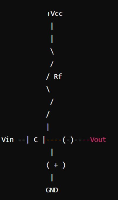
The ideal differentiator circuit consists of an op-amp with a capacitor CC connected in series with the input signal and a resistor RfR_f connected in the feedback loop. The configuration ensures that the output voltage is the derivative of the input voltage.
Circuit Diagram:
Expression for the Output Voltage
For an ideal op-amp differentiator, the output voltage Vout is given by:
Vout=−Rf*C*(dVin/dt)
Where:
- Vout is the output voltage.
- Rf is the feedback resistor.
- C is the capacitance.
- dVin/dt is the derivative of the input voltage with respect to time.
Input and Output Voltage Waveforms
In a differentiator circuit:
- If the input is a ramp signal, the output is a constant value.
- If the input is a sine wave, the output will be a cosine wave with a phase shift.
- If the input is a square wave, the output will be spikes at the transitions (rising and falling edges) of the square wave.
Output Voltage for a Square Wave Input
When a square wave is applied to the differentiator circuit:
- The output consists of sharp positive and negative spikes corresponding to the rising and falling edges of the square wave input.
- This occurs because the rate of change of a square wave is high at the transitions and zero elsewhere.
Output Voltage for a Sine Wave Input
For a sine wave input, the output of the differentiator will be a cosine wave. The amplitude of the output will be proportional to the frequency of the input sine wave and the values of RfR_f and CC.
Problems with Basic Differentiator Circuit
The basic differentiator circuit can exhibit certain problems:
- Noise Amplification: The circuit amplifies high-frequency noise, as differentiation emphasizes rapid changes in the input signal.
- Instability: Without proper frequency compensation, the circuit can become unstable and oscillate.
- Saturation: Large input signals or high-frequency components can cause the op-amp to saturate, leading to distortion in the output.
Practical Opamp as Differentiator
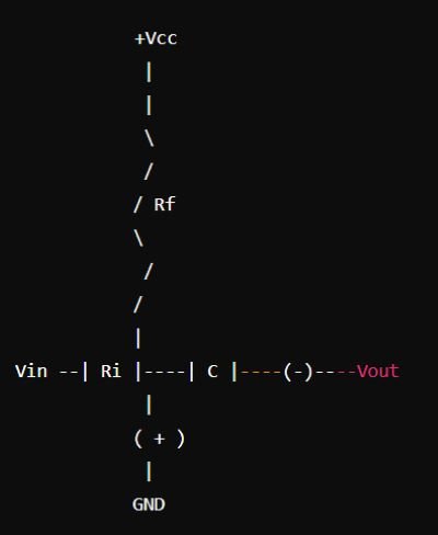
To address the problems of the ideal differentiator, a practical differentiator circuit includes a resistor Ri in series with the input capacitor. This addition reduces high-frequency gain and stabilizes the circuit.
Modified Circuit Diagram:
Advantages of Active Differentiator
- Linearity: The output is a linear function of the rate of change of the input signal.
- Stability: Adding a resistor in series with the input capacitor improves circuit stability.
- Enhanced Functionality: Useful in generating phase-shifted waveforms and detecting edges in digital signals.
Disadvantages of Active Differentiator
- Noise Sensitivity: Even in the practical design, the circuit remains sensitive to high-frequency noise.
- Complexity: Requires careful design and component selection to avoid instability and oscillation.
- Bandwidth Limitation: The addition of components like resistors and capacitors limits the circuit’s bandwidth.
Applications of Differentiator
- Edge Detection: Used in digital circuits to detect transitions in square waves or pulse signals.
- Signal Processing: Useful in extracting the high-frequency components of a signal.
- Analog Computation: Employed in analog computers to perform differentiation of analog signals.
- Frequency Modulation (FM) Detection: Used to demodulate FM signals in communication systems.
Difference Between Opamp Integrator and Differentiator
- Operation: An integrator produces an output proportional to the integral of the input, whereas a differentiator produces an output proportional to the derivative of the input.
- Circuit Configuration: The integrator has a capacitor in the feedback loop and a resistor at the input, while the differentiator has a capacitor at the input and a resistor in the feedback loop.
- Waveform Response: An integrator converts a square wave to a triangular wave, while a differentiator converts a square wave to a series of spikes.
Conclusion
The op-amp differentiator is a crucial circuit in analog signal processing, offering the ability to measure the rate of change of an input signal. While the ideal differentiator is simple, it is prone to noise and instability. A practical differentiator circuit, with additional components, can mitigate these issues and be effectively used in various applications, from edge detection to frequency modulation demodulation.