Simplifying Logic Circuits with Karnaugh Maps: Step-by-Step Tutorial
Karnaugh Mapping, or K-Map, is a systematic method used in logic design for simplifying Boolean functions. It provides a visual way to minimize logical expressions, making the implementation of digital circuits more efficient. By grouping ones (or zeros) in a grid, you can easily identify and eliminate redundant terms, leading to simpler and more cost-effective circuit designs.
What is the Karnaugh Map?
A Karnaugh Map is a graphical representation of a truth table. It consists of a grid where each cell represents a possible combination of input variables. The number of cells in the grid corresponds to the number of possible input combinations, typically following the formula 10², where n is the number of variables. The primary purpose of the K-Map is to visually identify groups of adjacent cells containing ones (for Sum of Products) or zeros (for Product of Sums). These groups are then used to create simplified Boolean expressions, minimizing the number of logic gates needed for implementation.
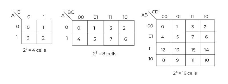
For example: to simplify the logic of the two inputs we require the k-map with the 4-cells (22=4). For a four-input logical expression, we need the 16-cell.
What is Gray Coding in Karnaugh Mapping?
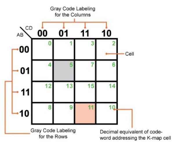
Gray coding is a binary numeral system used in Karnaugh Mapping to ensure that only one bit changes between adjacent cells. This minimizes the risk of errors during the simplification process and makes it easier to visually identify groups of adjacent ones or zeros. In a K-Map, the rows and columns are labeled using Gray code sequences, which ensures that each neighboring cell differs by only one variable.
For instance, in a two-variable K-Map, the binary numbers 00, 01, 11, and 10 are arranged in such a way that the transition from one cell to the next involves changing only one bit. This property of Gray code is crucial for correctly grouping cells during the minimization process, leading to more accurate and simplified Boolean expressions.
Understanding of Boolean Algebra and Logic Gates
Boolean Algebra is the foundation of digital logic design, dealing with binary variables that have two possible states: true (1) and false (0). It provides the mathematical framework for analyzing and simplifying logical expressions, which are built using basic logic gates like AND, OR, and NOT.
- AND Gate: Outputs true only if all its inputs are true.
- OR Gate: Outputs true if at least one of its inputs is true.
- NOT Gate: Inverts the input, outputting true if the input is false, and vice versa.
Understanding these basic gates and their combinations is essential for designing and optimizing digital circuits. More complex gates like NAND, NOR, XOR, and XNOR are derived from these basic operations and are used to build more advanced logic circuits.
Transitioning from Logic Expressions to Karnaugh Maps
Transitioning from logic expressions to Karnaugh Maps involves converting a Boolean expression or truth table into a visual representation. This process helps in identifying patterns and groups within the logic function, which can then be simplified.
- Start with a Boolean expression or a truth table that represents the logic function you want to simplify.
- Draw the Karnaugh Map (K-Map) corresponding to the number of variables in the expression. The number of cells in the K-Map will be 2n, where is the number of variables.
- Populate the K-Map by placing a 1 in the cells corresponding to the minterms (combinations of variables where the function outputs true) and Os elsewhere.
- Group the adjacent cells with ones in powers of two (e.g., 1, 2, 4) to form larger blocks. These groups will help in simplifying the Boolean expression.
This transition from logic expressions to K-Maps is crucial for circuit optimization, as it allows for the systematic reduction of terms, leading to simpler and more efficient circuit designs.
Steps to Optimize the Circuits with Karnaugh Mapping
Optimizing circuits using Karnaugh Maps involves several systematic steps that lead to a minimized Boolean expression and, consequently, a more efficient digital circuit:
- Draw the K-Map: Based on the number of variables in your logic function, draw the corresponding K-Map.
- Populate the K-Map: Enter the output values (1s and 0s) from your truth table or logic expression into the K-Map.
- Group the Ones (or Zeros): Identify and group adjacent cells containing ones (for SOP form) or zeros (for POS form). Groups must be in powers of two (1, 2, 4, 8, etc.).
- Create Simplified Terms: For each group, write down the simplified Boolean expression. Larger groups will result in more simplified terms.
- Combine the Terms: Combine the simplified terms to form the final minimized Boolean expression.
- Implement the Circuit: Use the simplified Boolean expression to design or re-design the circuit using the least number of logic gates.
Following these steps, the Karnaugh Map becomes a powerful tool for reducing the complexity of logic circuits, leading to designs that use fewer components, require less power, and operate more efficiently.
Understanding Karnaugh (K) Map with Example
To better understand the Karnaugh Map, let’s walk through an example.
Suppose you have a Boolean function F(A, B, C) defined by the following minterms: F (A,B,C) = Σ (1,3,5,7).
- Draw the K-Map: For three variables (A, B, C), the K-Map will have 8 cells.
- Label the K-Map: Label the rows and columns using Gray code sequences (00, 01, 11, 10).
- Populate the K-Map: Place a 1 in the cells corresponding to the minterms 1, 3, 5, and 7.
- Group the Ones: Identify adjacent groups of ones. In this example, you could group cells 1 and 3, and 5 and 7.
- Simplify the Expression: From the groups, derive the simplified Boolean expression. In this case, the simplified expression might be F=A′B+AC.
Through this example, you can see how the Karnaugh Map helps in visualizing and simplifying the Boolean expression, making it easier to design an efficient circuit.
Conclusion
Karnaugh Mapping is a fundamental technique in digital logic design that simplifies the process of minimizing Boolean expressions. By converting complex logic functions into a visual format, K-Maps allow designers to easily identify redundant terms and optimize circuits for efficiency. Understanding the underlying concepts of Boolean algebra and logic gates, along with the systematic approach of using Karnaugh Maps, enables the design of more cost-effective and reliable digital systems. Whether you are working with simple or complex logic functions, mastering Karnaugh Mapping is an essential skill for anyone involved in electronics and digital circuit design.
