Understanding Thyristors: Working, Types, Applications, and Protection
Thyristors are a class of semiconductor devices that act as switches, capable of handling high voltages and currents. They are widely used in power electronics to control the flow of electrical power. Essentially, a thyristor can switch from a non-conducting state to a conducting state when triggered by an external signal, making it an essential component in various electronic circuits.
What is a Thyristor?
A thyristor is a solid-state semiconductor device with four layers of alternating P and N-type materials (PNPN structure). It acts as a bistable switch, conducting when its gate receives a triggering current and continuing to conduct until the voltage across the device is reversed or reduced to zero.
The basic concept of a thyristor involves its ability to remain in an off state (non-conducting) until a small gate current is applied. Once triggered, the thyristor allows a large current to flow between its anode and cathode. This characteristic makes it highly effective in controlling power delivery in various applications.
Compared to other semiconductor devices like diodes and transistors, thyristors are unique in their ability to control high power levels with low input signals. While diodes allow current to flow in one direction and transistors can amplify signals, thyristors are specifically designed for switching and power control, providing a robust solution for managing high-power applications.
Symbol of Thyristor
The symbol of a thyristor resembles that of a diode with an added gate terminal. It consists of an anode (A), a cathode (K), and a gate (G). The anode and cathode represent the main terminals through which the current flows, while the gate controls the switching of the device.
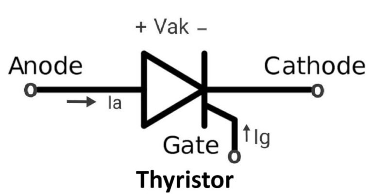
The diagram above illustrates the standard symbol for a thyristor. The arrow within the symbol points from the anode to the cathode, indicating the direction of conventional current flow when the device is in the conducting state. The gate terminal is shown as a line leading to the intersection of the anode and cathode paths, representing the control input.
Construction of Thyristor
Layers and Materials Used
A thyristor is constructed from four layers of semiconductor material, alternating between P-type and N-type. These layers form three PN junctions within the device. The typical materials used are silicon, due to its excellent electrical properties and ability to withstand high temperatures and voltages.
Detailed Construction Process
- Wafer Preparation: A silicon wafer is doped with impurities to create the alternating P and N layers.
- Layer Formation: The wafer is subjected to processes like diffusion or ion implantation to introduce the necessary dopants and form the PN junctions.
- Contact Formation: Metal contacts are added to the anode, cathode, and gate regions to facilitate electrical connections.
- Encapsulation: The wafer is then encapsulated in a protective package to shield it from environmental factors and mechanical damage.
Cross-Sectional Diagram
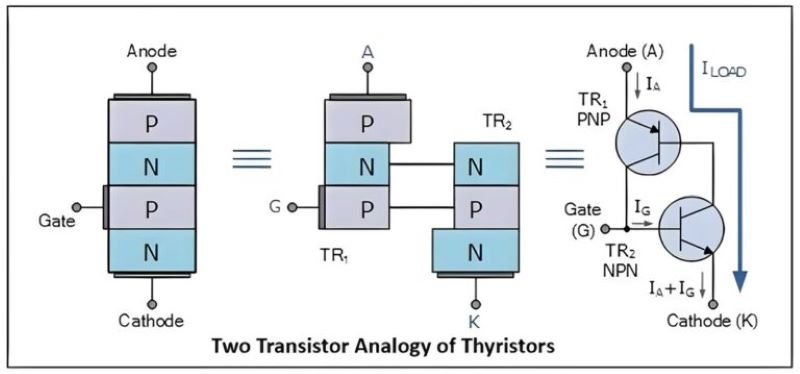
The cross-sectional diagram shows the internal structure of a thyristor, with the four layers (P1, N1, P2, N2) clearly labeled. The anode is connected to the P1 layer, the cathode to the N2 layer, and the gate to the P2 layer. The junctions between these layers are critical to the thyristor’s operation, allowing it to switch between conducting and non-conducting states when triggered.
Working Principle of Thyristor
Explanation of How a Thyristor Operates
A thyristor operates as a bistable switch, meaning it can switch between two stable states: on (conducting) and off (non-conducting). It remains in the off state until it is triggered by a gate signal. Once triggered, it allows current to flow from the anode to the cathode until the current drops below a certain threshold or the voltage is reversed.
Triggering Mechanisms
The triggering mechanism of a thyristor involves applying a small current to the gate terminal. This gate current initiates the conduction process by creating a flow of charge carriers, which breaks down the junction barrier and allows a large current to flow between the anode and cathode. Common triggering methods include:
- DC Gate Triggering: Applying a direct current to the gate.
- Pulse Gate Triggering: Using a pulse signal to trigger the gate.
- Light Triggering: In Light Activated SCRs (LASCR), light is used to trigger the thyristor.
On and Off States
- Off State (Blocking State): In this state, the thyristor blocks the current flow between the anode and cathode. It remains in this state until a gate pulse is applied.
- On State (Conducting State): When the gate current is applied, the thyristor enters the on state, allowing current to flow freely from the anode to the cathode. It remains in this state until the current falls below the holding current or the voltage is reversed.
Voltage and Current Characteristics
- Forward Blocking Voltage (V<sub>BO</sub>): The maximum voltage that can be applied to the thyristor in the off state without triggering it.
- Holding Current (I<sub>H</sub>): The minimum current required to keep the thyristor in the on state.
- Latching Current (I<sub>L</sub>): The minimum current required to latch the thyristor into the on state after the gate signal is removed.
- On-State Voltage Drop (V<sub>T</sub>): The voltage drop across the thyristor when it is in the on state, typically low to minimize power loss.
Types of Thyristors
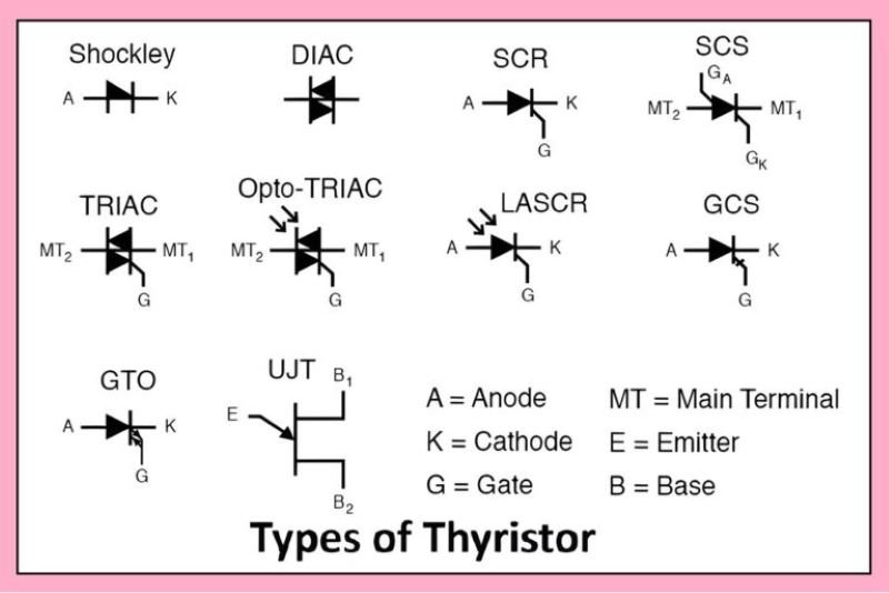
Thyristors come in various types, each designed for specific applications. The most common types include:
- SCR (Silicon Controlled Rectifier)
- TRIAC (Triode for Alternating Current)
- DIAC (Diode for Alternating Current)
- GTO (Gate Turn-Off Thyristor)
- Others (LASCR, RCT, etc.)
SCR (Silicon Controlled Rectifier)
- Description: A unidirectional device used primarily for rectification and switching.
- Applications: Motor speed controls, controlled rectifiers, and inverter circuits.
- Characteristics: High current and voltage ratings, requires a gate trigger to turn on, cannot turn off by the gate signal.
TRIAC (Triode for Alternating Current)
- Description: A bidirectional device capable of controlling AC power.
- Applications: Light dimmers, speed controls for fans and motors, and AC switching applications.
- Characteristics: Can conduct in both directions, triggered by both positive and negative gate signals, commonly used in AC circuits.
DIAC (Diode for Alternating Current)
- Description: A bidirectional trigger device used to trigger TRIACs.
- Applications: Triggering circuits for TRIACs, over-voltage protection.
- Characteristics: Symmetrical switching characteristics, used in conjunction with TRIACs for smooth switching.
GTO (Gate Turn-Off Thyristor)
- Description: A type of thyristor that can be turned off by a gate signal.
- Applications: High power inverters, choppers, and switching power supplies.
- Characteristics: Can be turned on and off by gate signals, used in high power applications.
Others (LASCR, RCT, etc.)
- LASCR (Light Activated SCR): Triggered by light, used in light-sensitive applications.
- RCT (Reverse Conducting Thyristor): Integrates a thyristor and a diode in reverse parallel, used in inverter circuits.
Operation of Thyristor
Firing Circuits and Methods
Firing circuits are used to provide the gate trigger signal to turn on the thyristor. Common methods include:
- R-C Firing Circuit: Uses resistors and capacitors to generate the gate pulse.
- UJT Firing Circuit: Uses a unijunction transistor to generate a precise triggering pulse.
- Pulse Transformer Firing: Isolates the control circuit from the power circuit and provides a high-voltage trigger pulse.
Commutation Techniques
Commutation refers to the process of turning off the thyristor. Techniques include:
- Natural Commutation: Occurs when the AC current naturally drops to zero.
- Forced Commutation: Involves using external circuits to force the current to zero, commonly used in DC circuits.
Turn-On and Turn-Off Characteristics
- Turn-On Time: The time required for the thyristor to switch from the off state to the on state after receiving the gate signal.
- Turn-Off Time: The time required for the thyristor to switch from the on state to the off state after the current falls below the holding current or a reverse voltage is applied.
Phase Control and Power Control Applications
Thyristors are extensively used in phase control applications to regulate power flow. Common applications include:
- Phase-Controlled Rectifiers: Used to control the output voltage of rectifiers by varying the firing angle.
- AC Voltage Controllers: Control the RMS voltage applied to loads, such as in light dimmers and motor speed controllers.
- Inverters and Converters: Used in power conversion systems to convert DC to AC and vice versa, providing controlled power delivery.
Protection of Thyristors
Overvoltage Protection
Overvoltage protection is crucial for safeguarding thyristors from voltage spikes that can cause premature failure. Common methods include:
- Transient Voltage Suppression (TVS) Diodes: Clamps voltage spikes to a safe level.
- Metal-Oxide Varistors (MOVs): Absorbs and dissipates transient energy.
- Zener Diodes: Provides a stable reference voltage and clamps excessive voltages.
Overcurrent Protection
Overcurrent protection ensures that the thyristor is not subjected to currents beyond its rated capacity. Techniques include:
- Fuses and Circuit Breakers: Interrupt the circuit when current exceeds a predetermined level.
- Current Limiting Resistors: Limits the current flow through the thyristor.
- Electronic Current Limiting Circuits: Monitors and controls current flow dynamically.
Snubber Circuits
Snubber circuits are used to protect thyristors from voltage transients and high dV/dt (rate of change of voltage). They typically consist of a resistor and capacitor in series, connected across the thyristor. Snubber circuits help in:
- Reducing Voltage Spikes: Damping oscillations and limiting voltage overshoots.
- Controlling dV/dt: Ensuring that the rate of voltage change does not exceed the thyristor’s capability.
Thermal Management
Effective thermal management is essential to prevent overheating and ensure reliable operation of thyristors. Methods include:
- Heat Sinks: Dissipate heat away from the thyristor.
- Forced Air Cooling: Uses fans to enhance heat dissipation.
- Liquid Cooling: Employs liquid coolants for high-power applications.
- Thermal Shutdown Circuits: Automatically turn off the thyristor when it exceeds a safe temperature.
Applications of Thyristors
Power Control in AC and DC Circuits
Thyristors are widely used in controlling power in both AC and DC circuits, providing efficient switching and regulation. Applications include:
- AC Voltage Controllers: Adjust the RMS voltage supplied to loads.
- DC Motor Drives: Regulate speed and torque in DC motors.
Motor Speed Control
Thyristors are essential in controlling the speed of electric motors by varying the voltage and current supplied to the motor. They are used in:
- Industrial Motor Drives: Precision control of large industrial motors.
- Consumer Appliances: Variable speed control in household appliances like mixers and fans.
Light Dimming
Thyristors are commonly used in light dimming circuits to control the brightness of incandescent and some types of LED lamps. They work by adjusting the phase angle of the AC supply to the lamp.
Power Conversion Systems
Thyristors play a crucial role in power conversion systems, including:
- Rectifiers: Convert AC to DC power for various applications.
- Inverters: Convert DC to AC power, essential for renewable energy systems like solar inverters.
Other Industrial and Consumer Applications
Thyristors are used in a wide range of industrial and consumer applications, such as:
- HVDC Transmission: Efficient long-distance power transmission.
- Welding Equipment: Controlling the power supplied to welding electrodes.
- Battery Chargers: Regulating the charging process for batteries.
Advantages and Disadvantages
Pros of Using Thyristors
- High Efficiency: Low power loss during switching.
- High Power Handling: Capable of managing high voltages and currents.
- Robustness: Durable and reliable in harsh environments.
- Precise Control: Accurate control of power delivery.
Cons and Limitations
- Complex Triggering: Requires precise gate control for reliable operation.
- Latching Current: Needs a minimum current to remain in the on state.
- Turn-Off Issues: Some types cannot be turned off by gate signal alone.
- Thermal Management: Needs effective cooling mechanisms to prevent overheating.
Conclusion
Summary of Key Points
Thyristors are critical components in modern electronics, providing efficient switching and power control capabilities. Their unique properties make them suitable for a wide range of applications, from motor control to power conversion systems. Understanding their working principle, types, operation, and protection mechanisms is essential for effective use.
Future Prospects and Advancements in Thyristor Technology
Future advancements in thyristor technology are likely to focus on:
- Improved Efficiency: Developing materials and designs that reduce power loss.
- Enhanced Control: Innovations in gate control mechanisms for more precise switching.
- Higher Power Ratings: Increasing the voltage and current handling capabilities.
- Integration with Smart Systems: Incorporating thyristors into IoT and smart grid applications for enhanced control and monitoring.
