Essential Electronic Components: Must-Known Basics for PCB Designers
Introduction
In the world of electronics, there are important people called PCB designers who create the blueprints for all sorts of gadgets and devices. These designers need to understand basic electronic parts to make sure everything works correctly. Think of these parts like the building blocks of electronics!
In this article, we’ll learn about some of these basic parts that every PCB designer should know about. From things like resistors to integrated circuits, each part has its own job to do in making electronic devices work.
Resistors
Resistors are fundamental components in electronic circuits that limit the flow of electric current. They are passive devices that dissipate electrical energy in the form of heat. By introducing resistance into a circuit, resistors help control the flow of current and voltage levels, ensuring the proper functioning of electronic devices.
There are various types of resistors available, each designed to meet specific requirements. Here are two common types:
1. Fixed Resistors
Fixed resistors, as the name suggests, have a predefined resistance value that cannot be adjusted. They are available in different packages, such as through-hole and surface mount, to suit various circuit designs. Fixed resistors are commonly used in applications where a stable and consistent resistance value is required.
2. Variable Resistors
Unlike fixed resistors, variable resistors allow for manual adjustment of the resistance value. These resistors, also known as potentiometers or rheostats, have a movable contact that can be adjusted to change the resistance. Variable resistors are ideal for applications where the resistance needs to be fine-tuned, such as volume controls in audio devices or brightness controls in lighting systems.
Factors to Consider When Selecting Resistors for PCB Designs
When selecting resistors for PCB designs, it is essential to consider several factors to ensure optimal performance and reliability. Here are some key considerations:
- Resistance Value: The resistance value is a crucial parameter when selecting resistors. It determines the amount of current that will flow through the circuit. It is important to choose a resistor with the appropriate resistance value to achieve the desired functionality and prevent excessive current flow.
- Power Rating: The power rating of a resistor indicates the maximum amount of power it can dissipate without overheating. It is crucial to select a resistor with a power rating that exceeds the expected power dissipation in the circuit. Failure to do so can lead to resistor failure or even damage to other components.
- Tolerance: Tolerance refers to the allowable variation in the resistance value of a resistor. It is essential to consider the tolerance when selecting resistors to ensure the accuracy and reliability of the circuit. Resistors with lower tolerance values provide more precise resistance values but may be more expensive.
- Temperature Coefficient: The temperature coefficient indicates how the resistance of a resistor changes with temperature. It is important to consider the temperature coefficient, especially in applications where the resistor will be subjected to varying temperature conditions. Choosing a resistor with a low temperature coefficient ensures stability and accuracy in such situations.
- Package Size: The package size of a resistor is an important consideration, especially in space-constrained PCB designs. It is crucial to select resistors that fit within the available space while also considering the ease of assembly and solderability.
Capacitors
Capacitors are electronic components that store and release electrical energy. They are widely used in various electronic devices and circuits, playing a crucial role in their proper functioning. Understanding the different types of capacitors and their characteristics is essential for effective PCB design.
At their core, capacitors consist of two conductive plates separated by a dielectric material. When a voltage is applied across the plates, an electric field is created, causing opposite charges to accumulate on each plate. This accumulation of charge creates an electric potential difference, or voltage, between the plates.
The amount of charge that a capacitor can store is determined by its capacitance, which is measured in farads (F). The capacitance value of a capacitor is determined by factors such as the surface area of the plates, the distance between them, and the properties of the dielectric material. There are several types of capacitors available in the market, each with its own set of characteristics and applications. Here are two commonly used types:
Ceramic Capacitors
Ceramic capacitors are the most widely used type of capacitors due to their small size, low cost, and high capacitance values. They are made of a ceramic material with metal electrodes on either side. Ceramic capacitors are available in various capacitance values and voltage ratings, making them suitable for a wide range of applications.
These capacitors are known for their stability, reliability, and low leakage current. They are commonly used in filtering, decoupling, and bypass applications in electronic circuits.
Electrolytic Capacitors
Electrolytic capacitors are polarized capacitors that use an electrolyte as one of the electrodes. They are known for their high capacitance values and are often used in applications that require large amounts of capacitance. Electrolytic capacitors are available in both aluminum and tantalum variants.
These capacitors have a higher voltage rating compared to ceramic capacitors and are commonly used in power supply circuits, audio amplifiers, and other applications where high capacitance values are required.
Capacitor Characteristics for PCB Design
When designing a PCB, it is important to consider the following capacitor characteristics:
Capacitance
The capacitance of a capacitor determines its ability to store electrical charge. It is measured in farads (F) and represents the amount of charge stored per volt of applied voltage. The capacitance value required for a specific application depends on the circuit’s requirements and the desired performance.
It is important to select a capacitor with the appropriate capacitance value to ensure proper functioning of the circuit. Capacitance values for capacitors can range from picofarads (pF) to microfarads (uF) or even higher.
Voltage Rating
The voltage rating of a capacitor indicates the maximum voltage that can be applied across its terminals without causing damage. Exceeding the voltage rating can lead to capacitor failure or even explosion. It is important to select a capacitor with a voltage rating that is higher than the maximum voltage expected in the circuit.
When designing a PCB, it is crucial to consider the voltage requirements of the circuit and select capacitors with appropriate voltage ratings to ensure reliability and safety.
Other Considerations
In addition to capacitance and voltage rating, there are other factors to consider during PCB design:
- Size and footprint: The physical size and footprint of the capacitor should be compatible with the PCB layout and assembly process.
- Temperature coefficient: Some capacitors exhibit changes in capacitance with temperature. It is important to consider the temperature coefficient of the capacitor if the circuit operates in extreme temperature conditions.
- Equivalent series resistance (ESR): ESR affects the performance of capacitors in high-frequency applications. It is important to select capacitors with low ESR for such applications.
By considering these capacitor characteristics during PCB design, you can ensure the proper functioning and reliability of your electronic circuits.
Inductors
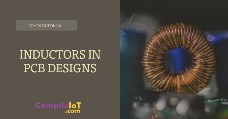
An inductor is a passive electronic component that stores energy in the form of a magnetic field. It consists of a coil of wire wound around a core material, typically made of iron or ferrite. When an electric current flows through the coil, a magnetic field is generated, and energy is stored in this field.
Inductors are commonly represented by the symbol “L” in circuit diagrams. They are measured in units called henries (H), named after the physicist Joseph Henry, who made significant contributions to the study of electromagnetism.
Types of Inductors Commonly Used in PCB Designs
There are several types of inductors commonly used in PCB designs, each with its own characteristics and applications. Let’s take a look at two popular types:
1. Wirewound Inductors
Wirewound inductors are one of the most commonly used types of inductors in PCB designs. They are made by winding a wire around a core material, such as a ferrite rod or a powdered iron core. Wirewound inductors offer high inductance values and low resistance, making them suitable for applications that require high current handling and low losses.
These inductors are often used in power supply circuits, RF circuits, and audio applications. Their robust construction and ability to handle high currents make them ideal for applications where efficiency and reliability are crucial.
2. Ferrite Bead Inductors
Ferrite bead inductors, also known as ferrite beads or ferrite chokes, are another common type of inductor used in PCB designs. They are made by threading a wire through a ferrite bead, which is a ceramic material with high magnetic permeability.
Ferrite bead inductors are primarily used for noise suppression and EMI filtering. They work by absorbing high-frequency noise and preventing it from reaching sensitive components or radiating from the circuit. Their small size and high impedance at high frequencies make them ideal for applications where space is limited and noise reduction is critical.
Considerations for Selecting and Placing Inductors on PCBs
When selecting and placing inductors on a PCB, there are several important considerations to keep in mind:
- Inductance Value: The inductance value of an inductor determines its ability to store energy. It is crucial to select an inductor with the appropriate inductance value for the specific application. The required inductance can vary depending on factors such as the desired frequency response, current requirements, and the overall circuit design.
- Current Rating: Inductors have a maximum current rating, which indicates the maximum amount of current they can handle without significant performance degradation or overheating. It is important to choose an inductor that can handle the expected current levels in the circuit to ensure reliable operation.
- Size and Package: The size and package of an inductor are crucial considerations, especially in space-constrained PCB designs. It is important to choose an inductor that fits within the available space on the PCB without interfering with other components or signal paths. Additionally, the package type should be compatible with the assembly process and soldering requirements.
- EMI Considerations: If the circuit is sensitive to electromagnetic interference (EMI) or if the circuit itself generates EMI, it is important to select inductors with appropriate EMI suppression capabilities. Ferrite bead inductors are particularly effective in reducing high-frequency noise and should be considered in such applications.
- Placement and Routing: The placement and routing of inductors on a PCB can significantly impact their performance. It is important to consider the proximity of inductors to other components, especially those that are sensitive to magnetic fields. Proper routing of traces and minimizing the loop area can help reduce unwanted coupling and improve overall circuit performance.
Diodes
A diode is a two-terminal electronic component that allows current to flow in one direction while blocking it in the opposite direction. It acts as a one-way valve for electric current, making it an essential building block in many electronic circuits.
The basic structure of a diode consists of a semiconductor material, typically silicon or germanium, with two regions: the P-region (positive) and the N-region (negative). The junction between these two regions is known as the PN junction, which forms the heart of a diode and determines its behavior.
There are several types of diodes, each designed for specific purposes. Let’s take a look at some common types:
1. Rectifier Diodes
Rectifier diodes are primarily used to convert alternating current (AC) into direct current (DC). They allow current to flow in one direction, blocking the reverse current. This is crucial in applications such as power supplies and battery chargers, where a steady DC voltage is required.
2. Zener Diodes
Zener diodes are used for voltage regulation and voltage reference. They are designed to maintain a constant voltage across their terminals, even when the current varies. Zener diodes are commonly used in voltage regulators, surge protectors, and as voltage references in electronic circuits.
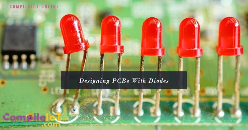
3. Light Emitting Diodes (LEDs)
LEDs are diodes that emit light when current passes through them. They are widely used in lighting applications, displays, and indicators. LEDs are energy-efficient, have a long lifespan, and are available in various colors, making them versatile components in electronic designs.
4. Schottky Diodes
Schottky diodes are known for their low forward voltage drop and fast switching characteristics. They are commonly used in high-frequency applications, such as RF circuits, rectifiers, and power supplies. Schottky diodes are also used in solar panels to prevent reverse current flow.
5. Varactor Diodes
Varactor diodes, also known as varicap diodes, are used for voltage-controlled capacitance. They are commonly used in voltage-controlled oscillators, frequency synthesizers, and tuning circuits. Varactor diodes find applications in wireless communication systems and frequency modulation (FM) radios.
Applications of Diodes in PCB Designs
Printed Circuit Boards (PCBs) are widely used in electronic devices, and diodes are an integral part of PCB designs. Here are some common applications of diodes in PCB designs:
- Power Supply Circuitry: Diodes are used in power supply circuits to rectify AC voltage and convert it into DC voltage. They ensure a steady and reliable power supply to the various components on the PCB, preventing damage due to voltage fluctuations.
- Signal Processing and Conditioning: Diodes are used in signal processing and conditioning circuits to manipulate and shape electrical signals. They can be used for signal rectification, clipping, and amplitude modulation, ensuring accurate signal transmission and processing.
- Voltage Regulation: PCB designs often incorporate voltage regulators to provide a stable power supply to the components. Zener diodes are commonly used as voltage references and regulators in these circuits, ensuring a consistent voltage level despite fluctuations in the input voltage.
- Protection Circuits: Diodes are used in protection circuits to safeguard sensitive components from voltage spikes and reverse current. By incorporating diodes as reverse polarity protection or transient voltage suppressors, the PCB can be protected from potential damage.
Transistors

A transistor is a semiconductor device that can amplify or switch electronic signals and electrical power. It is a fundamental component of integrated circuits (ICs) and is widely used in electronic devices such as computers, smartphones, televisions, and more. Transistors come in different types, including bipolar junction transistors (BJTs) and field-effect transistors (FETs). Each type has its own unique characteristics and applications.
There are two primary types of transistors: bipolar junction transistors (BJTs) and field-effect transistors (FETs). Let’s take a closer look at each of them:
Bipolar Junction Transistors (BJTs)
BJTs are the most common type of transistors. They consist of three layers of semiconductor material: the emitter, the base, and the collector. BJTs are further classified into two types: NPN (Negative-Positive-Negative) and PNP (Positive-Negative-Positive).
NPN transistors are widely used as switching devices. When a small current flows from the base to the emitter, a larger current flows from the collector to the emitter, allowing the transistor to act as an electronic switch. On the other hand, PNP transistors are commonly used in amplification circuits.
Field-Effect Transistors (FETs)
FETs are another important type of transistor. They are constructed using a different principle than BJTs and are known for their high input impedance and low output impedance. FETs consist of three terminals: the source, the gate, and the drain.
There are two main types of FETs: Junction FETs (JFETs) and Metal-Oxide-Semiconductor FETs (MOSFETs). JFETs are primarily used in low-noise amplifiers and analog switches, while MOSFETs are widely used in digital circuits and power amplifiers.
Practical Examples of Transistor Usage in PCB Designs
Transistors find extensive application in PCB designs across various industries. Let’s explore a few practical examples:
- Switching Circuits: Transistors act as electronic switches, allowing or blocking the flow of current in a circuit. They are widely used in applications such as power supplies, motor control, and digital logic circuits.
- Amplification Circuits: Transistors are also crucial components in amplification circuits. They can significantly increase the strength of electronic signals, enabling them to drive speakers, antennas, or other output devices. Amplification circuits utilizing transistors are commonly found in audio systems, radio receivers, and communication devices.
- Signal Processing: Transistors play a vital role in signal processing within PCB designs. They can modify, filter, or condition signals to suit specific requirements. Signal processing circuits using transistors are used in applications such as audio equalizers, filters, and modulation circuits.
Integrated Circuits

Integrated Circuits (ICs) are the building blocks of modern electronics. These tiny electronic components have revolutionized the field of electronics by packing multiple electronic components onto a single chip. This integration allows for smaller and more efficient devices, making ICs an essential part of everyday technology.
ICs revolutionized the field of electronics by enabling the miniaturization and integration of electronic components. Before the advent of ICs, electronic circuits were built using discrete components, which were bulky, expensive, and prone to failure. ICs made it possible to create smaller, more reliable, and more cost-effective electronic devices.
There are various types of Integrated Circuits, each designed for specific applications. Here are two common types:
1. Microcontrollers
Microcontrollers are ICs that contain a microprocessor, memory, and input/output peripherals on a single chip. They are widely used in embedded systems, such as consumer electronics, industrial automation, and automotive applications.
Microcontrollers are programmable and can execute specific tasks based on the program stored in their memory. They are commonly used to control and monitor devices, process data, and interface with other electronic components.
2. Operational Amplifiers (Op-Amps)
Operational Amplifiers, or Op-Amps, are ICs that are used to amplify and manipulate analog signals. They are commonly used in audio amplifiers, signal conditioning circuits, and analog-to-digital converters.
Op-Amps are versatile components that can perform various mathematical operations on signals, such as amplification, filtering, and mixing. They are essential in analog circuit design and are widely used in many electronic devices.
Guidelines for Selecting, Integrating, and Placing ICs on PCB Layouts
When designing a Printed Circuit Board (PCB) layout, careful consideration must be given to the selection, integration, and placement of ICs. Here are some guidelines to follow:
1. Selecting ICs
Consider the following factors when selecting ICs for your PCB design:
- Functionality: Choose ICs that meet the specific requirements and functionality of your electronic device.
- Specifications: Review the datasheets of ICs to ensure they meet the required voltage, current, speed, and temperature specifications.
- Package Type: Select ICs with package types that are compatible with your PCB layout and assembly process.
- Availability: Ensure that the selected ICs are readily available from reliable suppliers.
2. Integrating ICs
Integrating ICs into your PCB design involves connecting them to other components and circuits. Follow these guidelines:
- Schematic Design: Create a clear and well-organized schematic diagram that shows the connections between ICs and other components.
- Signal Integrity: Pay attention to signal integrity issues, such as impedance matching, noise reduction, and proper grounding.
- Power Supply: Ensure that ICs receive a stable and clean power supply to prevent malfunctions and damage.
- Decoupling Capacitors: Place decoupling capacitors near ICs to reduce noise and stabilize the power supply.
3. Placing ICs on PCB Layouts
The placement of ICs on a PCB layout is crucial for optimal performance and manufacturability. Consider the following guidelines:
- Component Density: Arrange ICs to maximize component density while maintaining proper clearances and avoiding signal interference.
- Heat Dissipation: Ensure that ICs have adequate space for heat dissipation, especially for power-hungry or heat-sensitive components.
- Signal Routing: Plan the routing of signals between ICs to minimize signal degradation, crosstalk, and electromagnetic interference.
- Manufacturability: Consider the ease of assembly and soldering when placing ICs, ensuring accessibility for inspection and rework if needed.
Conclusion
In conclusion, Understanding basic electronic components is fundamental for PCB designers. It enables you to design efficient and reliable circuits, troubleshoot and debug effectively, and explore innovative solutions. However, it is crucial to remember that learning is a lifelong process in the field of electronics. Embrace the opportunity to continuously expand your knowledge and skills, and you will become a more proficient and successful PCB designer.