Difference between Coplanar Waveguide, Stripline, Microstrip & Other Planar Transmission Lines in PCB
Coplanar waveguide, stripline and microstrip are three commonly used transmission line technologies. Each of these technologies has its own advantages and disadvantages, making them suitable for different applications. In this article, we will explore the differences between coplanar waveguide, stripline, and microstrip and discuss their characteristics and applications.
What are Planar Transmission Lines?
A planar transmission line is a type of transmission line that is constructed on a flat surface, typically a printed circuit board (PCB). Unlike traditional transmission lines, which are three-dimensional and require bulky coaxial cables or waveguides, planar transmission lines are compact and can be integrated directly onto the PCB. This integration allows for efficient signal transmission and reduces the overall size and complexity of electronic systems.
Types of Planar Transmission Lines
There are several types of planar transmission lines commonly used in electronic systems:
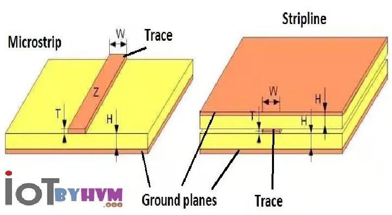
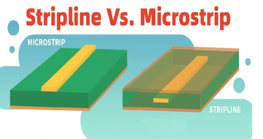
1. Microstrip: Microstrip transmission lines consist of a conducting strip placed on one side of a dielectric substrate, with a ground plane on the other side. They are widely used in microwave circuits and are relatively easy to fabricate.
2. Stripline: Stripline transmission lines consist of a conducting strip sandwiched between two dielectric layers, with ground planes on both sides. They offer better shielding and lower radiation compared to microstrip lines, making them suitable for high-frequency applications.
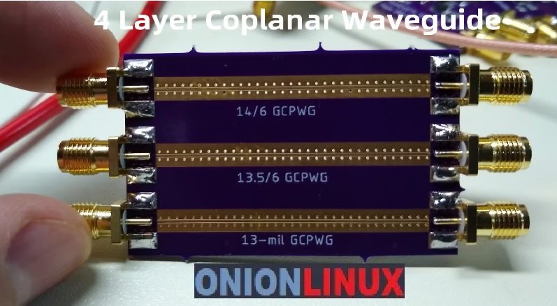
3. Coplanar Waveguide: Coplanar waveguide transmission lines consist of a conducting strip placed on a dielectric substrate, with ground planes on both sides. They offer excellent signal isolation and are commonly used in high-speed digital circuits.
Understanding Coplanar Waveguide (CPW)

The Coplanar Waveguide (CPW) is a type of planar transmission line that consists of a central conductor sandwiched between two ground planes. The central conductor is typically wider than the ground planes, and it is separated from them by a dielectric material. This unique structure offers several advantages over other types of transmission lines.
The Structure of Coplanar Waveguide (CPW)
CPW consists of a conducting strip placed on a dielectric substrate, with a ground plane on either side. The conducting strip and the ground planes are all on the same plane, hence the name “coplanar.” This unique structure gives CPW several advantages over other transmission line types.
The conducting strip in CPW is typically made of a highly conductive material such as copper, while the dielectric substrate is made of materials like FR-4 or Rogers. The ground planes on either side of the conducting strip provide a return path for the signal, reducing radiation and improving signal integrity.
Characteristics of Coplanar Waveguide (CPW)
CPW offers several key characteristics that make it a popular choice for high-frequency applications:
- Wide Bandwidth: CPW has a wide bandwidth, allowing for the transmission of high-frequency signals without significant loss or distortion. This makes it suitable for applications that require a broad range of frequencies.
- Low Loss: CPW exhibits low insertion loss, meaning that the signal experiences minimal attenuation as it travels along the transmission line. This is crucial for maintaining signal integrity and maximizing the efficiency of electronic systems.
- Low Radiation: The coplanar structure of CPW helps to confine the electromagnetic fields within the transmission line, reducing radiation and minimizing interference with nearby components. This is especially important in densely packed electronic systems.
- Easy Integration: CPW is compatible with standard fabrication processes used in the semiconductor industry, making it easy to integrate into complex electronic circuits. It can be easily connected to other components, such as amplifiers, filters, and antennas.
- Design Flexibility: CPW allows for easy adjustment of the characteristic impedance by varying the dimensions of the conducting strip and the spacing between the strip and the ground planes. This flexibility enables designers to optimize the performance of the transmission line for specific applications.
Applications of Coplanar Waveguide (CPW)
CPW finds applications in various industries, including:
1. RF and Microwave Systems: CPW is widely used in RF and microwave systems, such as satellite communication, radar systems, and wireless networks. Its low loss and wide bandwidth make it suitable for high-frequency signal transmission over long distances.
2. High-Speed Digital Circuits: With the increasing demand for high-speed data transfer, CPW is becoming a popular choice for high-speed digital circuits. It is used in applications such as high-speed data buses, memory interfaces, and signal integrity testing.
3. Integrated Circuits: CPW is commonly used in the design of integrated circuits, where it serves as a transmission line for interconnecting various components. Its easy integration and design flexibility make it an ideal choice for on-chip communication.
4. Sensors and Detectors: CPW is also employed in the field of sensors and detectors. It is used in applications such as biosensors, gas sensors, and temperature sensors, where it provides efficient signal transmission and high sensitivity.
5. Millimeter-Wave Systems: CPW is well-suited for millimeter-wave systems, which operate in the frequency range of 30 GHz to 300 GHz. Its low loss and wide bandwidth make it an excellent choice for applications such as automotive radar, wireless backhaul, and 5G communication.
Microstrip Structure and Characteristics

The microstrip transmission line is a type of planar transmission line that consists of a conducting strip separated from a ground plane by a dielectric substrate. It is widely used in microwave and RF applications due to its compact size, low cost, and ease of fabrication. They can support high-frequency signals with low loss and good impedance matching. The characteristic impedance of a microstrip line depends on the dimensions of the strip, the dielectric constant of the substrate and the thickness of the dielectric layer.
Microstrip lines also exhibit some inherent limitations. One of the main challenges is the dispersion effect, which causes the propagation velocity of the signal to vary with frequency. This can lead to distortion and signal degradation, especially at high frequencies. Additionally, microstrip lines are susceptible to radiation and coupling with nearby structures, which can result in unwanted interference and crosstalk.
Applications of Microstrip Transmission Lines
Microstrip transmission lines find a wide range of applications in various fields, including telecommunications, aerospace, and radar systems. Some common applications of microstrip lines are:
- Printed Circuit Boards (PCBs): Microstrip lines are commonly used for routing high-frequency signals on PCBs. They provide a compact and cost-effective solution for interconnecting components and devices.
- Antennas: Microstrip patch antennas are widely used in wireless communication systems. They offer a low-profile design and can be easily integrated into portable devices.
- Filters and Couplers: Microstrip lines are used in the design of microwave filters and couplers. They provide a compact and efficient solution for frequency selective devices.
- RFID Tags: Microstrip lines are used in the design of RFID (Radio Frequency Identification) tags. They enable wireless communication between the tag and the reader.
Stripline Structure and Characteristics

Stripline is another type of planar transmission line that consists of a conducting strip sandwiched between two dielectric layers, with ground planes on both sides. Unlike microstrip lines, stripline offers better shielding and isolation from external electromagnetic interference. The conducting strip is completely surrounded by dielectric material, which helps to contain the electromagnetic fields within the structure. This makes stripline suitable for applications that require high levels of isolation and minimal interference.
Stripline also offers better impedance control compared to microstrip lines. The characteristic impedance of a stripline is primarily determined by the dimensions of the conducting strip and the dielectric constant of the substrate. By carefully designing these parameters, the characteristic impedance can be accurately controlled to match the requirements of a specific application.
Applications of Stripline Transmission Lines
Stripline transmission lines are commonly used in applications that require high levels of isolation and low radiation. Some examples of applications include:
- High-Speed Digital Systems: Stripline is used in high-speed digital systems, such as computer motherboards and backplanes, to ensure signal integrity and minimize electromagnetic interference.
- Microwave Filters: Stripline is widely used in the design of microwave filters, such as bandpass filters and low-pass filters. The shielding properties of stripline help to minimize unwanted coupling and improve filter performance.
- Radar Systems: Stripline is used in the design of radar systems, where high levels of isolation and low radiation are critical for accurate signal detection and processing.
Other Planar Transmission Lines
In addition to microstrip and stripline, there are other types of planar transmission lines that offer unique characteristics and applications. Some examples include coplanar waveguide (CPW), slotline, and suspended stripline. CPW is a type of transmission line that consists of a conducting strip separated from two ground planes by a dielectric substrate. It offers a wider bandwidth and lower dispersion compared to microstrip and stripline. CPW is commonly used in high-frequency applications, such as millimeter-wave systems and wireless communication.
Slotline is a transmission line that consists of a narrow slot cut in a ground plane, with a dielectric substrate on top. It offers low radiation and good isolation, making it suitable for applications that require high levels of shielding and minimal interference. Slotline is commonly used in microwave filters and couplers.
Suspended stripline is a transmission line that consists of a conducting strip suspended between two ground planes, with a dielectric material supporting the strip. It offers low radiation and good isolation, similar to stripline. Suspended stripline is commonly used in high-frequency applications, such as satellite communication and radar systems.
Each type of planar transmission line has its own advantages and limitations, and the choice of transmission line depends on the specific requirements of the application.
Comparison between Coplanar, Stripline and Micro
Now, let’s compare coplanar waveguide, stripline, and microstrip in terms of their characteristics and applications:
1. Transmission Line Structure:
- Coplanar waveguide: Signal conductor sandwiched between two ground planes.
- Stripline: Signal conductor sandwiched between two dielectric layers.
- Microstrip: Signal conductor placed on one side of a dielectric substrate.
2. Loss:
- Coplanar waveguide: Low loss.
- Stripline: Low loss.
- Microstrip: Higher loss compared to coplanar waveguide and stripline.
3. Bandwidth:
- Coplanar waveguide: Wide bandwidth.
- Stripline: Wide bandwidth.
- Microstrip: Relatively narrower bandwidth compared to coplanar waveguide and stripline.
4. Isolation:
- Coplanar waveguide: Good isolation between adjacent transmission lines.
- Stripline: Good isolation.
- Microstrip: Lower isolation compared to coplanar waveguide and stripline.
5. Radiation:
- Coplanar waveguide: Moderate radiation.
- Stripline: Low radiation.
- Microstrip: Higher radiation compared to coplanar waveguide and stripline.
6. Shielding:
- Coplanar waveguide: No shielding required.
- Stripline: Good shielding.
- Microstrip: Lower shielding compared to coplanar waveguide and stripline.
7. Impedance:
- Coplanar waveguide: Controlled impedance.
- Stripline: Controlled impedance.
- Microstrip: Controlled impedance with some limitations.
8. Power Handling:
- Coplanar waveguide: High power handling capabilities.
- Stripline: Moderate power handling capabilities.
- Microstrip: Lower power handling compared to coplanar waveguide and stripline.
9. Applications:
- Coplanar waveguide: Microwave and millimeter-wave circuits, high-isolation circuits, high-power circuits.
- Stripline: High-frequency circuits, circuits requiring low radiation and good isolation, circuits requiring controlled impedance.
- Microstrip: Low-frequency and high-frequency circuits, cost-sensitive circuits, circuits requiring flexibility and compact size.
Conclusion
In conclusion, coplanar waveguide, stripline, and microstrip are three different transmission line technologies, each with its own set of advantages and applications. The choice of transmission line depends on the specific requirements of the circuit, such as bandwidth, loss, isolation, radiation, shielding, impedance, power handling, and cost. By understanding the differences between these technologies, designers can make informed decisions and optimize their circuit designs for optimal performance.


