What is RF Circuit Design?
RF (Radio Frequency) circuit design is a specialized field that deals with the design and implementation of circuits that operate at high frequencies. These circuits are essential for various wireless communication systems, such as mobile phones, Wi-Fi routers, and satellite communication devices. In this article we will explore about RF Circuit designs and their importance.
What is RF Circuit Design?
RF circuit design refers to the process of designing circuits that operate in the radio frequency (RF) range. RF circuits are used in a wide range of applications, including wireless communication systems, radar systems, satellite communication, and many more. These circuits are designed to handle high-frequency signals and are crucial for the functioning of various electronic devices.
RF circuit design involves the careful selection and integration of various components, such as amplifiers, filters, mixers, oscillators, and antennas. The goal is to design a circuit that can efficiently transmit, receive, and process RF signals while minimizing interference and maximizing performance.
The Importance of RF Circuit Design
RF circuit design plays a crucial role in the development of wireless communication systems and other RF applications. It is essential to design circuits that can efficiently transmit and receive RF signals while minimizing interference and maximizing performance. A well-designed RF circuit can ensure reliable and high-quality communication, improve signal integrity, and optimize power efficiency.
Key Considerations in RF Circuit Design
When designing RF circuits, several factors need to be taken into consideration. Here are some key considerations:
- Frequency Range: The frequency range of the circuit is a fundamental consideration in RF circuit design. Different applications require specific frequency ranges, and the circuit design must be tailored to operate within the desired range. The choice of frequency range affects the selection of components, circuit layout, and overall performance of the circuit.
- Impedance Matching: Impedance matching is crucial in RF circuit design to ensure efficient power transfer between components and minimize signal reflections. Proper impedance matching helps maximize power transfer and improves overall circuit performance. Techniques such as using transmission lines, matching networks, and impedance transformers are employed to achieve impedance matching in RF circuits.
- Noise and Interference: In RF circuit design, minimizing noise and interference is vital to maintain signal integrity and maximize the signal-to-noise ratio. Various sources of noise and interference, such as thermal noise, intermodulation distortion, and electromagnetic interference, can degrade the performance of RF circuits. Design techniques such as shielding, filtering, and proper grounding are employed to mitigate these issues.
- Power Efficiency: Power efficiency is a critical consideration in RF circuit design, especially in battery-powered devices. Efficient power management techniques, such as power amplification, voltage regulation, and power control, are employed to optimize power consumption and extend battery life.
- Component Selection: The selection of components is crucial in RF circuit design. Components such as amplifiers, filters, mixers, and oscillators must be carefully chosen to meet the requirements of the circuit. Factors such as gain, bandwidth, noise figure, linearity, and frequency stability need to be considered when selecting components for RF circuits.
The RF Circuit Design Process
The RF circuit design process typically involves the following steps:
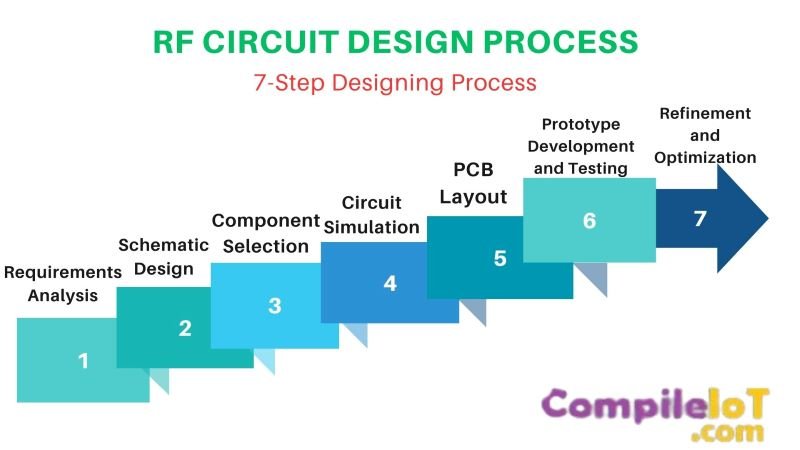
Requirements Analysis
Understanding the requirements of the RF circuit is the first step in the design process. This includes determining the desired frequency range, power levels, signal quality, and other specifications.
Schematic Design
Based on the requirements, a schematic diagram of the circuit is created. The schematic represents the interconnection of components and their electrical characteristics.
Component Selection
Appropriate components are selected based on the circuit requirements. This involves considering factors such as frequency range, gain, noise figure, and other specifications.
Circuit Simulation
The circuit is simulated using specialized software to analyze its performance. Simulation helps identify any issues, optimize the design, and verify that the circuit meets the desired specifications.
PCB Layout
Once the circuit design is finalized, it is translated into a printed circuit board (PCB) layout. The PCB layout involves placing the components and routing the traces to ensure proper signal flow and minimize interference.
Prototype Development and Testing
A prototype of the circuit is built and tested to validate its performance. Testing involves measuring parameters such as gain, noise figure, frequency response, and power consumption.
Refinement and Optimization
Based on the test results, the circuit design is refined and optimized to meet the desired specifications. This may involve making changes to component values, layout modifications, or further simulation and testing iterations.
RF Circuit Types
There are several types of RF circuits, each serving a specific purpose in the overall system. Let’s explore some of the common RF circuit types:
1. RF Amplifiers
RF amplifiers are used to increase the power of the radio frequency signals. They play a vital role in boosting weak signals received from antennas and ensuring their successful transmission to the next stage of the circuit. RF amplifiers are crucial in maintaining the signal strength and improving the overall system performance.
2. RF Filters
RF filters are designed to selectively allow certain frequencies to pass through while attenuating or blocking others. They are used to eliminate unwanted noise and interference from the received signals. RF filters ensure that only the desired frequency components are processed, improving the signal quality and minimizing the impact of external disturbances.
3. RF Mixers
RF mixers are essential in frequency conversion processes. They combine two or more input signals to produce an output signal with a different frequency. RF mixers are commonly used in applications such as frequency upconversion and downconversion, modulation, and demodulation. They enable the integration of different frequency bands and facilitate signal processing in various wireless communication systems.
4. RF Oscillators
RF oscillators generate stable and precise radio frequency signals. These signals serve as a reference for the entire RF circuit and are used for modulation, demodulation, and frequency synthesis. RF oscillators are crucial for maintaining accurate frequency and timing in wireless communication systems, ensuring reliable data transmission and reception.
5. RF Modulators and Demodulators
RF modulators and demodulators are responsible for the encoding and decoding of information onto the radio frequency carrier signal. Modulators convert the baseband signal into an RF signal suitable for transmission, while demodulators extract the original baseband signal from the received RF signal. These circuits are essential for various modulation schemes used in wireless communication, such as amplitude modulation (AM), frequency modulation (FM), and phase modulation (PM).
RF Circuits vs Analog Circuits vs Digital Circuits
RF Circuits
RF stands for Radio Frequency, and RF circuits are designed to work with signals in the radio frequency range. These circuits are commonly used in wireless communication systems, such as radios, televisions, mobile phones, and Wi-Fi devices. They are responsible for transmitting and receiving signals over long distances.
Analog Circuits
Analog circuits are designed to process continuous signals. These circuits work with voltages and currents that vary continuously, allowing for smooth and precise representation of real-world quantities. Analog circuits are commonly used in audio and video systems, sensors, and measurement devices.
Digital Circuits
Digital circuits, on the other hand, work with discrete signals that have only two possible states: high and low, or 1 and 0. These circuits are the foundation of modern computing and information processing systems. They are used in computers, smartphones, digital cameras, and many other digital devices.
| Aspects | RF Circuits | Analog Circuits | Digital Circuits |
| Signal Type | Radio Frequency | Continuous | Discrete |
| Signal Representation | Waveform | Voltage or Current Level | Binary Code |
| Applications | Wireless Communication Systems, Radios, Televisions, Wi-Fi Devices | Audio and Video Systems, Sensors, Measurement Devices | Computers, Smartphones, Digital Cameras, Digital Devices |
| Processing Speed | High | Medium | Very High |
| Complexity | Medium | High | Very High |
| Power Consumption | Medium | Medium | Low |
Conclusion
In conclusion, RF circuit design is a specialized field that plays a crucial role in the development of wireless communication systems and other RF applications. By considering factors such as frequency range, impedance matching, noise and interference, power efficiency, and component selection, engineers can design RF circuits that meet the desired specifications and deliver reliable and high-quality performance.