How To Write a Driver for Hardware (STM32, I2C, Datasheet)
Writing drivers is a crucial aspect of embedded systems development, which enables communication between hardware devices and the software running on the microcontroller. In this article, we will delve into the process of writing a driver for an I2C (Inter-Integrated Circuit) peripheral device on the STM32 microcontroller, using the device’s datasheet as a reference.
Understanding the I2C Protocol
Before we begin writing the driver, it is essential to understand the fundamentals of the I2C protocol. I2C is a serial communication protocol that allows multiple devices to communicate over the same bus using only two wires: Serial Data Line (SDA) and Serial Clock Line (SCL).
The I2C protocol employs a master-slave architecture, where a single master device initiates and controls the communication, while one or more slave devices respond to the master’s requests. Each device on the I2C bus has a unique 7-bit or 10-bit address, allowing the master to communicate with specific slaves.
I2C Communication Modes
The I2C protocol supports several communication modes, including:
- Master Transmitter Mode: The master transmits data to a slave device.
- Master Receiver Mode: The master receives data from a slave device.
- Slave Transmitter Mode: A slave transmits data to the master.
- Slave Receiver Mode: A slave receives data from the master.
I2C Transfer Formats
Communication on the I2C bus is carried out using specific transfer formats, which include:
- Start Condition: Initiated by the master to indicate the beginning of a transfer.
- Stop Condition: Initiated by the master to indicate the end of a transfer.
- Repeated Start Condition: Initiated by the master to begin a new transfer without relinquishing control of the bus.
- Acknowledge (ACK): A single-bit response sent by the receiver to indicate successful reception of data.
- Not Acknowledge (NACK): A single-bit response sent by the receiver to indicate unsuccessful reception of data or to terminate a transfer.
I2C Addressing
Each device on the I2C bus has a unique address, which consists of a fixed part (determined by the device manufacturer) and a configurable part (set by the user). The address is typically 7 bits long, but some devices support 10-bit addressing for compatibility with future extensions of the protocol.
Reading the Datasheet
Before writing a driver, it is crucial to thoroughly read and understand the datasheet of the peripheral device you are working with. The datasheet contains valuable information about the device’s specifications, electrical characteristics, communication protocols, register maps, and timing requirements.
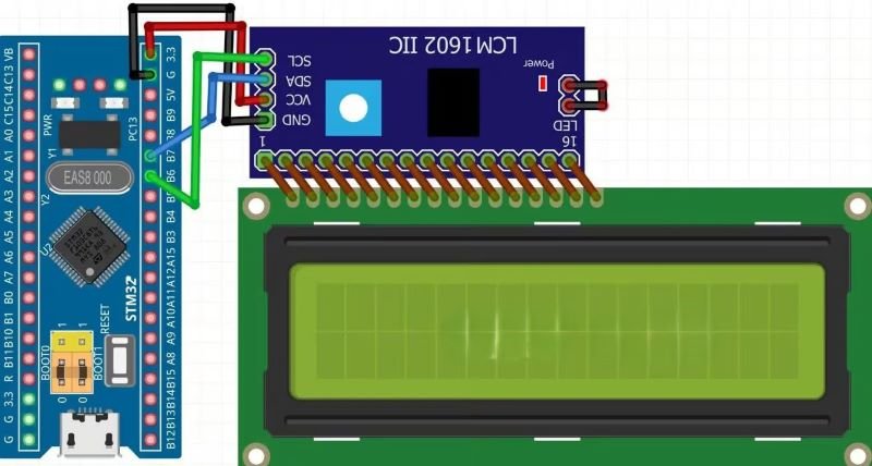
When reading the datasheet, pay close attention to the following sections:
- Electrical Characteristics: Information about the device’s operating voltages, currents, and other electrical parameters.
- Communication Protocol: Details the communication protocol(s) supported by the device, such as I2C, SPI, or UART. In our case, we will focus on the I2C protocol.
- Register Map: Describes the device’s internal registers, their addresses, and the functions they control.
- Timing Diagrams: Illustrates the timing requirements for various operations, such as read and write cycles, setup and hold times, and clock frequencies.
Writing the I2C Driver
Now that we have a solid understanding of the I2C protocol and the peripheral device’s datasheet, we can proceed with writing the driver code.
Step 1: Initialize the I2C Peripheral
Before we can communicate with the peripheral device, we need to initialize the I2C peripheral on the STM32 microcontroller. This typically involves the following steps:
- Enable the clock for the I2C peripheral.
- Configure the I2C peripheral settings, such as clock speed, addressing mode, and general call mode.
- Enable the I2C peripheral.
Here’s an example of how to initialize the I2C peripheral in C:
#include "stm32f4xx_hal.h" // Replace with the appropriate header file for your STM32 family

void I2C_Initialize(void)
{
// Enable the clock for the I2C peripheral
__HAL_RCC_I2C1_CLK_ENABLE();

// Configure the I2C peripheral
hi2c1.Instance = I2C1;
hi2c1.Init.ClockSpeed = 100000; // Set the I2C clock speed (in Hz)
hi2c1.Init.Dutycycle = I2C_DUTYCYCLE_2; // Set the duty cycle
hi2c1.Init.OwnAddress1 = 0x00; // Set the device's own address (not used in master mode)
hi2c1.Init.AddressingMode = I2C_ADDRESSINGMODE_7BIT; // Set the addressing mode (7-bit or 10-bit)
hi2c1.Init.DualAddressMode = I2C_DUALADDRESS_DISABLE; // Disable dual addressing mode
hi2c1.Init.OwnAddress2 = 0x00; // Set the second own address (not used)
hi2c1.Init.GeneralCallMode = I2C_GENERALCALL_DISABLE; // Disable general call mode
hi2c1.Init.NoStretchMode = I2C_NOSTRETCH_DISABLE; // Disable clock stretching mode

// Initialize the I2C peripheral
if (HAL_I2C_Init(&hi2c1) != HAL_OK)
{
// Handle initialization error
}
}
Step 2: Write Data to the Peripheral Device
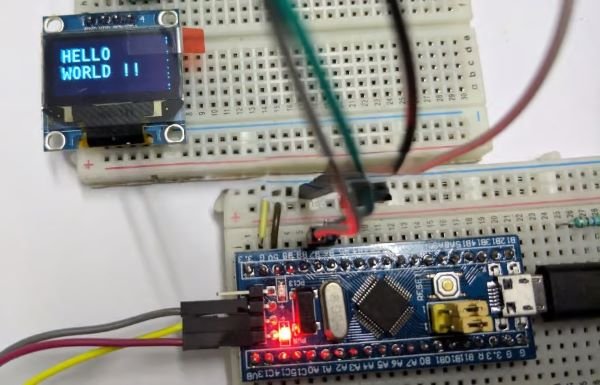
To write data to the peripheral device, we need to follow the I2C master transmitter mode protocol. Here’s an example of how to write data to a device:
uint8_t data[] = {0x01, 0x02, 0x03}; // Data to be written
uint8_t deviceAddress = 0x40; // Address of the peripheral device

HAL_StatusTypeDef status = HAL_I2C_Master_Transmit(&hi2c1, deviceAddress, data, sizeof(data), HAL_MAX_DELAY);

if (status != HAL_OK)
{
// Handle transmission error
}
In this example, we create an array data containing the values we want to write to the peripheral device. We then call the HAL_I2C_Master_Transmit function, passing the I2C handle, the device address, the data buffer, the length of the data, and a timeout value.
Step 3: Read Data from the Peripheral Device
To read data from the peripheral device, we need to follow the I2C master receiver mode protocol. Here’s an example of how to read data from a device:
uint8_t readBuffer[10]; // Buffer to store the received data
uint8_t deviceAddress = 0x40; // Address of the peripheral device
uint8_t numBytesToRead = 5; // Number of bytes to read

HAL_StatusTypeDef status = HAL_I2C_Master_Receive(&hi2c1, deviceAddress, readBuffer, numBytesToRead, HAL_MAX_DELAY);

if (status != HAL_OK)
{
// Handle reception error
}
In this example, we create a buffer readBuffer to store the received data. We then call the HAL_I2C_Master_Receive function, passing the I2C handle, the device address, the receive buffer, the number of bytes to read, and a timeout value.
Step 4: Handle Interrupts and Callbacks
In some cases, you may need to handle interrupts and callbacks to manage I2C communication events. The STM32 HAL (Hardware Abstraction Layer) provides several callback functions that you can implement to handle these events.
For example, you can implement the HAL_I2C_MasterTxCpltCallback function to handle the completion of a master transmit operation, or the HAL_I2C_MasterRxCpltCallback function to handle the completion of a master receive operation.
void HAL_I2C_MasterTxCpltCallback(I2C_HandleTypeDef *hi2c)
{
// Handle master transmit completion
}

void HAL_I2C_MasterRxCpltCallback(I2C_HandleTypeDef *hi2c)
{
// Handle master receive completion
}
Conclusion
In conclusion, writing an I2C driver for the STM32 microcontroller involves understanding the I2C protocol, thoroughly reading the device’s datasheet and then implementing the necessary code to initialize the I2C peripheral, write data to and read data from the peripheral device. By following these steps and using the HAL library, you can effectively communicate with I2C devices in your embedded systems projects.
