Exploring IGBT-Based Induction Heater Circuits
Induction heating is a widely used technique in industries for processes like metal hardening, melting, and brazing. This method relies on electromagnetic induction to generate heat directly within a material, making it highly efficient and precise. Among various technologies used in induction heating circuits, the Insulated Gate Bipolar Transistor (IGBT) stands out for its efficiency, reliability, and ability to handle high-frequency operations. This article explores a simple IGBT-based induction heater circuit, its working principle, and its applications.
What is an IGBT?
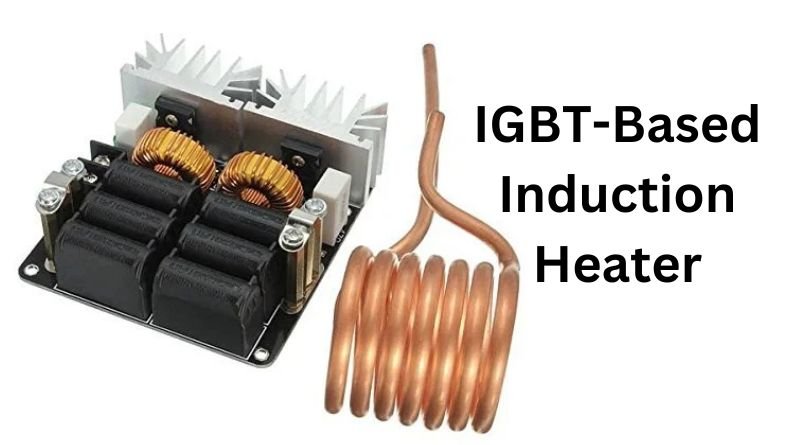
The Insulated Gate Bipolar Transistor (IGBT) is a semiconductor device that combines the high-speed switching capabilities of a Metal Oxide Semiconductor Field Effect Transistor (MOSFET) with the high current-handling capacity of a Bipolar Junction Transistor (BJT). It is a three-terminal device with a gate, collector, and emitter.
The working principle of an IGBT involves controlling the current flow between the collector and emitter by applying a voltage to the gate. When a positive voltage is applied to the gate relative to the emitter, it creates a conductive channel, allowing current to flow. The device efficiently switches on and off at high speeds, making it ideal for power electronics applications.
Advantages of IGBT in High-Frequency Applications
- High Efficiency: IGBTs have low conduction losses, enabling efficient operation in high-power circuits.
- High-Speed Switching: They support rapid switching, crucial for high-frequency induction heating.
- Thermal Stability: IGBTs can handle significant power levels with minimal heat dissipation.
- Compact Design: Their integration allows for compact and lightweight circuit designs.
Induction Heating Basics
Explanation of the Induction Heating Process
Induction heating works by generating an alternating magnetic field through a coil. When a conductive material, such as metal, is placed within this field, eddy currents are induced in the material. The resistance of the material to these currents produces heat. This non-contact heating method ensures uniform heating and is highly efficient.
Key Components and Principles Involved
- Induction Coil: Generates the alternating magnetic field.
- Workpiece: The material to be heated, usually metallic.
- Resonant Circuit: Maintains high-frequency oscillations for efficient heating.
- Power Supply: Provides the required voltage and current to the circuit.
- Control Circuit: Regulates the frequency and power output, often incorporating an IGBT for switching.
Circuit Diagram
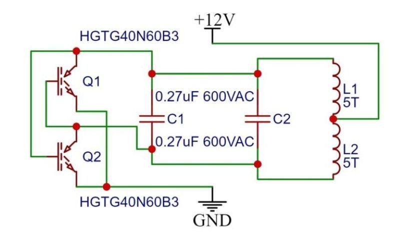
An IGBT-based induction heater circuit is designed to create a high-frequency alternating magnetic field for efficient heating of a target material. Below is an explanation of the key components and their roles in the circuit:
Key Components and Their Functions
- IGBT (HGTG40N60B3):
- The Insulated Gate Bipolar Transistor (IGBT) is the heart of the circuit, acting as a fast-switching device to control the high-frequency current through the induction coil.
- The specific IGBT used here (HGTG40N60B3) has a high voltage and current rating, making it suitable for high-power applications.
- Film Capacitor (0.27 µF, 600 VAC):
- These capacitors are used in the resonant LC circuit for tuning the circuit to the desired operating frequency.
- They also help in improving power factor and efficiency by ensuring effective energy utilization.
- Induction Coil:
- The coil, consisting of 5+5 turns, generates the alternating magnetic field required for induction heating.
- When an alternating current flows through the coil, it induces eddy currents in the nearby target material, causing it to heat up.
- Power Supply (12V):
- A 12V power supply with adequate current capacity drives the circuit.
- It provides the energy needed for the IGBT and the induction coil to operate effectively.
- Driver Circuit:
- The driver circuit controls the switching of the IGBT, ensuring it operates at the desired frequency.
- It includes components that regulate the gate voltage of the IGBT for efficient operation.
- Resonant Tank Circuit (LC Circuit):
- The combination of the induction coil and capacitors forms the LC tank circuit.
- The resonant frequency of the circuit is tuned to approximately 182 kHz, which optimizes the heating process for the target material.
Working Principle
Working Overview
- Power Flow: The power supply provides energy to the circuit, which is modulated by the driver circuit to control the IGBT.
- Magnetic Field Generation: The high-frequency switching of the IGBT causes the induction coil to produce a rapidly alternating magnetic field.
- Heating Process: Eddy currents are induced in the target material, and the resistance of the material converts these currents into heat.
- Resonance: The LC tank circuit ensures that the system operates at its most efficient frequency, maximizing energy transfer and minimizing losses.
Step-by-Step Explanation of How the Circuit Operates
- Power Supply: The circuit receives DC power, which is converted from AC if necessary.
- Oscillator Circuit: A high-frequency signal is generated, usually via an LC resonant circuit.
- Induction Coil and Capacitor: The coil and capacitor work together to maintain resonance, ensuring efficient power transfer.
- IGBT Operation: The IGBT switches the current through the coil at high frequencies, creating a dynamic magnetic field.
- Induced Currents: The magnetic field induces eddy currents in the workpiece, generating heat.
- Feedback and Control: The feedback circuit monitors the system, ensuring stable operation and protecting the components.
Role of the IGBT in Controlling High-Frequency Current
The IGBT acts as the primary switching element in the circuit, rapidly alternating between on and off states. This switching action regulates the high-frequency current through the induction coil, enabling precise control over the heating process. Its ability to handle high voltages and currents with minimal loss makes it indispensable for efficient operation.
Component Selection
Guidelines for Choosing the Right IGBT and Other Critical Components
- IGBT Selection: Choose an IGBT with the following characteristics:
- Voltage Rating: Ensure it can handle the maximum voltage in the circuit, typically 1.5 times the supply voltage.
- Current Rating: Select an IGBT capable of managing the peak current during operation.
- Switching Speed: Opt for devices with high switching frequencies to ensure smooth operation in high-frequency induction heating applications.
- Capacitors:
- Use high-quality, low-ESR capacitors for the resonant circuit to maintain stable oscillations.
- Ensure the voltage rating exceeds the operating voltage.
- Induction Coil:
- Select a coil material with low resistance to reduce energy losses.
- Adjust the coil’s turns and dimensions to match the desired operating frequency.
- Diodes and Snubber Circuit:
- Use fast recovery diodes to protect the IGBT from voltage spikes.
- Include snubber circuits to suppress transient voltages.
Factors to Consider Like Power Rating, Frequency, and Efficiency
- Power Rating: Match all components to the maximum power requirements of the system to prevent overheating or failure.
- Frequency: Ensure components are optimized for the desired operational frequency to avoid inefficiency or resonance issues.
- Thermal Management: Incorporate proper heat sinks or cooling systems to dissipate heat effectively.
Design Considerations
Challenges in Designing an IGBT-Based Induction Heater
- Thermal Management: Excessive heat generation can damage the IGBT and other components.
- Resonance Stability: Maintaining a stable resonant frequency is critical for efficient operation.
- High Voltage Spikes: Voltage transients can degrade components without proper protection mechanisms.
- Electromagnetic Interference (EMI): High-frequency operation can cause EMI, affecting nearby devices.
Tips for Ensuring Safety and Reliability
- Use appropriate heat sinks and cooling fans for thermal stability.
- Include overcurrent and overvoltage protection circuits to safeguard the system.
- Employ shielding to minimize EMI.
- Ensure proper insulation between high-voltage and low-voltage sections.
Applications
Common Use Cases for IGBT-Based Induction Heaters
- Metal Hardening: Induction heaters are used to harden metal parts in automotive and machinery industries.
- Melting and Smelting: Efficient for melting metals like aluminum and gold in foundries.
- Brazing and Soldering: Ideal for joining metals in electronics and plumbing applications.
- Cooking Equipment: Used in induction cooktops for fast and efficient heating.
Industries and Scenarios Where They Are Most Effective
- Automotive: Heat treatment of gears, shafts, and other components.
- Aerospace: Fabrication of high-precision parts.
- Electronics: Soldering and desoldering of electronic components.
- Medical: Manufacturing of surgical tools and equipment sterilization.
Advantages and Limitations
Benefits of This Circuit Over Other Designs
- High Efficiency: Minimal energy loss due to precise control.
- Compact Size: Smaller footprint compared to traditional heating systems.
- Rapid Heating: Quickly reaches target temperatures.
- Non-Contact Heating: Reduces wear and tear on components.
Limitations and Potential Improvements
- Cost: High-quality IGBTs and components can be expensive.
- Complexity: Designing and maintaining the circuit requires technical expertise.
- Thermal Management: Heat dissipation remains a challenge at higher power levels.
Potential Improvements:
- Use advanced IGBTs with better thermal performance.
- Implement digital control systems for enhanced accuracy.
- Develop modular designs for easy scalability and maintenance.
Conclusion
In conclusion, IGBT-based induction heater circuits offer a versatile and efficient solution for various industrial and commercial heating applications. By carefully selecting components and addressing design challenges, these systems can achieve high performance and reliability. Whether it’s in manufacturing, electronics, or even cooking, this technology continues to evolve, opening new possibilities for innovation. Induction heating with IGBTs represents the future of sustainable and efficient thermal processing.
FAQs
1. What is the role of an IGBT in an induction heater circuit?
The IGBT acts as a high-speed switch that controls the current through the induction coil. Its ability to handle high frequencies and power levels makes it an essential component for efficient operation and precise control in the circuit.
2. Why is a resonant LC circuit used in induction heating?
The resonant LC circuit ensures that the system operates at a specific frequency, maximizing energy transfer to the workpiece. This resonance helps achieve efficient heating while minimizing power loss.
3. Can I use a MOSFET instead of an IGBT in an induction heater?
While MOSFETs are suitable for low to medium power applications, IGBTs are better for high-power and high-frequency operations due to their lower conduction losses and higher current-handling capacity.
4. How do I ensure the safety of the IGBT in the circuit?
To protect the IGBT, use snubber circuits to suppress voltage spikes, implement proper heat sinks for thermal management, and include overcurrent and overvoltage protection mechanisms.
5. What are the advantages of using an induction heater over traditional heating methods?
Induction heating is non-contact, highly efficient, and precise. It eliminates the need for open flames or heating elements, reducing energy consumption and improving safety and speed in heating applications.


