DIY Proximity Sensor Circuit with LED Bar-Graph: A Complete Tutorial
If you’re working with robotics project or an automatic lighting system, a proximity sensor can be an invaluable tool. This tutorial will show you how to build a proximity sensor circuit with an LED bar-graph display. The circuit provides a clear and immediate visual representation of object distance, making it easy to integrate into your next DIY project. We’ll cover everything from the working principle to testing and applications.
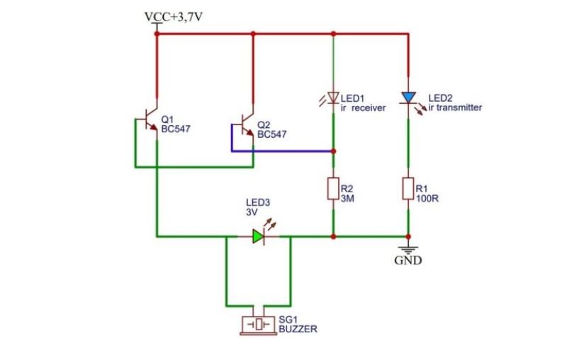
BJT Based IR Proximity Sensor Circuit
Circuit Components
- NPN Transistor (e.g., BC547)
- IR LED (Infrared Emitter)
- Photodiode (Infrared Detector)
- Resistors (1kΩ, 10kΩ)
- Capacitor (10µF)
- LED (Indicator)
- Power Supply (5V DC)
- Breadboard and Connecting Wires
Working Principle
In this circuit, an IR LED emits infrared light, which is invisible to the human eye. The photodiode is positioned to detect the reflected IR light when an object is nearby. When no object is in the vicinity, the photodiode does not receive any reflected light, and the transistor remains off. However, when an object comes close, the IR light reflects back to the photodiode, causing it to conduct. This changes the base voltage of the transistor, turning it on. As a result, the LED indicator lights up, signaling the presence of an object.
Steps to Build the Circuit
- Assemble the Components: Place the IR LED and photodiode on the breadboard. Ensure they are aligned such that the photodiode can detect the IR light reflected from nearby objects.
- Connect the Transistor: Connect the photodiode to the base of the NPN transistor through a 10kΩ resistor. The emitter of the transistor is grounded, and the collector is connected to the positive rail via a 1kΩ resistor.
- Add the Indicator LED: Connect an LED between the collector of the transistor and ground, ensuring it lights up when the transistor conducts.
- Power the Circuit: Connect the power supply (5V) to the IR LED and the transistor circuit. The circuit is now ready to detect objects.
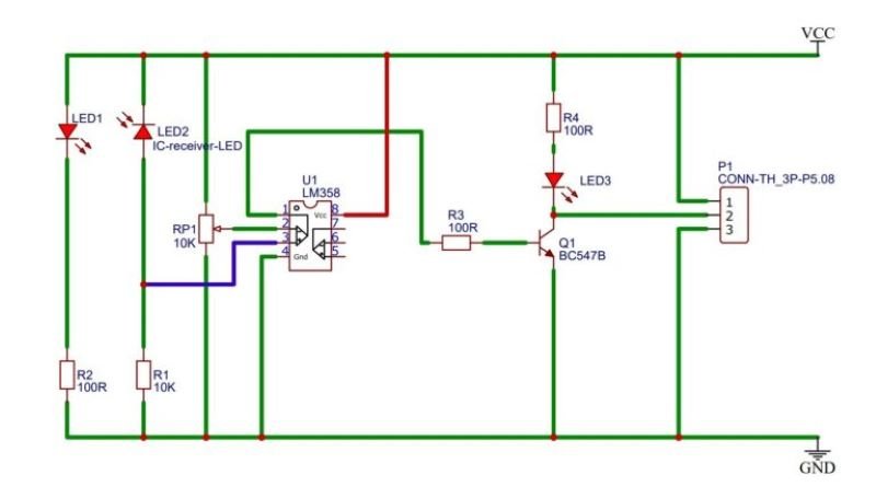
Proximity Sensor by LM358 IC
Circuit Components
- LM358 Dual Op-Amp IC
- IR LED (Infrared Emitter)
- Photodiode (Infrared Detector)
- Resistors (1kΩ, 10kΩ, 100kΩ)
- Potentiometer (10kΩ)
- Capacitor (10µF)
- LED (Indicator)
- Power Supply (5V DC)
- Breadboard and Connecting Wires
Working of Proximity Sensor by LM358
The LM358 IC is used as a comparator in this circuit. One of the op-amps in the LM358 compares the voltage across the photodiode with a reference voltage set by the potentiometer. When an object is near, the photodiode receives the reflected IR light, causing a voltage change. If this voltage exceeds the reference voltage, the output of the op-amp goes high, turning on the LED indicator. This indicates the presence of an object.
Steps to Build the Circuit
- Setup the IR LED and Photodiode: Place the IR LED and photodiode on the breadboard, ensuring they are aligned for proper detection.
- Connect the LM358 IC: Insert the LM358 IC on the breadboard. Connect the photodiode to the inverting input of the op-amp (pin 2) through a resistor. Connect the non-inverting input (pin 3) to the potentiometer, which sets the reference voltage.
- Configure the Output: Connect the output of the op-amp (pin 1) to an LED through a 1kΩ resistor. The LED will serve as the indicator.
- Power the Circuit: Connect the power supply (5V) to the IC and the IR LED circuit. Adjust the potentiometer to fine-tune the sensitivity of the proximity sensor. The circuit is now ready for operation.
These two IR proximity sensor circuits demonstrate simple and effective ways to detect nearby objects using basic electronic components.
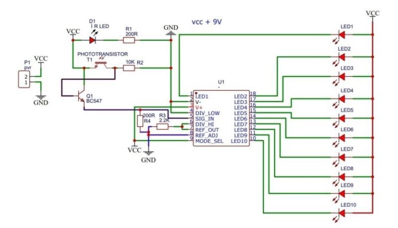
Proximity Sensor Circuit with LED Bar-Graph
Circuit Components
- IR LED (Infrared Emitter)
- Photodiode (Infrared Detector)
- LM3914 IC (LED Bar-Graph Driver)
- Resistors (1kΩ, 10kΩ)
- Potentiometer (10kΩ)
- Capacitor (10µF)
- LED Bar-Graph Display (10 LEDs)
- Power Supply (5V DC)
- Breadboard and Connecting Wires
IR Proximity Sensor Working Principle
The IR proximity sensor operates by emitting infrared light from the IR LED, which reflects off nearby objects and is detected by the photodiode. The intensity of the reflected light depends on the distance of the object, with closer objects reflecting more light. The photodiode converts this reflected light into an electrical signal, which varies in voltage based on the proximity of the object. This voltage signal is then processed and displayed using an LED bar-graph, providing a visual indication of the object’s distance.
Signal Processing and Display
The varying voltage from the photodiode is fed into the LM3914 IC, which is designed to drive an LED bar-graph display. The LM3914 reads the input voltage and lights up the corresponding number of LEDs on the bar-graph, indicating the proximity of the object. For example, if the object is very close, most or all of the LEDs will light up, whereas if the object is far away, fewer LEDs will be illuminated. The potentiometer is used to adjust the sensitivity of the sensor, allowing for fine-tuning of the distance measurement.
Steps to Build the Circuit
- Assemble the IR Sensor: Place the IR LED and photodiode on the breadboard, positioning them to detect reflected infrared light from nearby objects.
- Connect the LM3914 IC: Insert the LM3914 IC onto the breadboard. Connect the output of the photodiode to the signal input pin of the LM3914 (pin 5).
- Configure the LED Bar-Graph Display: Connect the LED bar-graph display to the output pins (10 through 18) of the LM3914. Each pin corresponds to one LED in the bar-graph.
- Add Power Supply: Connect a 5V power supply to the IR LED, photodiode, and LM3914 IC. Use a 10kΩ potentiometer to set the reference voltage for the LM3914, controlling the threshold at which the LEDs light up.
- Fine-Tune the Circuit: Adjust the potentiometer to set the desired sensitivity of the proximity sensor. Ensure all connections are secure and double-check the circuit for any errors.
Testing the Circuit
After building the circuit, test it by placing objects at varying distances from the IR sensor. Observe the LED bar-graph display to ensure it accurately reflects the distance of the objects. Adjust the potentiometer if necessary to improve the sensitivity and response of the sensor. The circuit should light up more LEDs as the object gets closer and fewer LEDs as the object moves further away.
Proximity Sensor Applications
- Obstacle Detection in Robotics: The proximity sensor can be used in robots to detect obstacles and navigate around them.
- Automatic Lighting Systems: It can be integrated into automatic lighting systems, where lights turn on or off based on the proximity of a person.
- Security Systems: The sensor can detect unauthorized entry by sensing the presence of a person or object near doors or windows.
- Industrial Automation: In manufacturing, proximity sensors can be used to detect the presence of objects on a conveyor belt, ensuring proper processing.
Conclusion
In conclusion, the proximity sensor circuit with an LED bar-graph display is a practical and visually intuitive way to measure and display the distance of nearby objects. Using basic components like an IR LED, photodiode, and LM3914 IC, this circuit provides a scalable solution for various applications, from robotics to security systems. By following the steps to build and test the circuit, you can create a reliable proximity sensor that offers clear visual feedback through the LED bar-graph.