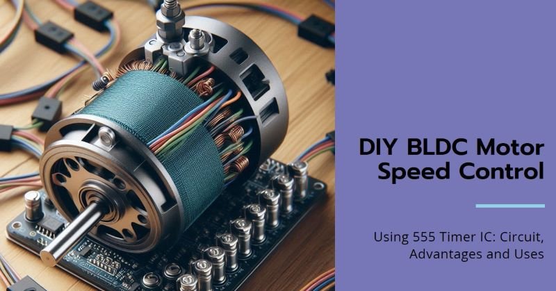
DIY BLDC Motor Speed Control Using 555 Timer IC: Circuit, Advantages and Uses
A Brushless DC (BLDC) motor is widely used in modern applications due to its high efficiency, reliability, and ability to deliver precise control in various industries. These motors are particularly popular in sectors like automotive, robotics, and aerospace, where smooth, noiseless, and efficient operation is required. To effectively drive a BLDC motor, a driver circuit is essential, and one such simple yet powerful approach involves the use of a 555 Timer IC. This versatile IC, with its ability to generate Pulse Width Modulation (PWM) signals, can efficiently control the speed and performance of BLDC motors, making it an ideal choice for motor driver circuits. Let’s see what exactly Is a BLDC Motor!
What is a BLDC Motor?
A Brushless DC motor is a type of electric motor that operates without the use of brushes to transfer electrical energy to the rotor. Instead, it relies on an electronic controller to switch current through the motor windings, which generates a rotating magnetic field that drives the motor’s rotor. The absence of brushes reduces mechanical wear, increases lifespan, and enhances efficiency compared to traditional brushed motors.
Explanation of the Working Principle of BLDC Motors
BLDC motors are powered by DC electricity but are driven by alternating currents in the stator. The stator contains several coils arranged in a circular pattern. When current flows through the stator windings, it creates a magnetic field that interacts with permanent magnets on the rotor. The electronic controller switches the current between the windings in a precise sequence, causing the rotor to rotate in sync with the magnetic field.
The speed and direction of the motor are controlled by adjusting the timing of the current pulses and the strength of the magnetic field.
Advantages of BLDC Motors Over Traditional Brushed Motors
BLDC motors offer several advantages over their brushed counterparts:
- High Efficiency: BLDC motors provide higher power output and efficiency due to the lack of friction from brushes.
- Low Maintenance: Without brushes to wear out, BLDC motors require less maintenance and have a longer operational life.
- Better Speed Control: Electronic commutation allows for more precise control of motor speed and torque.
- Quiet Operation: BLDC motors operate more quietly than brushed motors, making them ideal for applications where noise is a concern.
- Heat Management: Since the windings are on the stator, they can be cooled more effectively than the rotor windings in brushed motors.
Key Components of a BLDC Motor
- Rotor: The moving part of the motor, typically equipped with permanent magnets.
- Stator: The stationary part of the motor, consisting of windings where the current is passed to create a magnetic field.
- Electronic Controller: Manages the commutation of current between stator windings, ensuring the rotor’s magnetic alignment.
- Hall Sensors (optional): Detect the rotor’s position and provide feedback to the controller for precise operation.
Overview of the 555 Timer IC
The 555 Timer IC is one of the most versatile and widely used integrated circuits in electronics. It can be configured in various modes to generate accurate timing pulses, square waves, or PWM signals, which are essential in controlling devices such as motors, lights, and more. This IC operates with a small number of external components and can be powered by a wide range of voltages, making it ideal for use in motor driver circuits.
Key Modes of Operation
- Astable Mode: In this mode, the 555 Timer continuously switches between high and low states, producing a square wave output. This is useful for generating oscillations, such as in PWM signal generation for motor control.
- Monostable Mode: In monostable mode, the 555 Timer produces a single output pulse of a defined length in response to a trigger. This is typically used for timing purposes.
- Bistable Mode: The bistable mode allows the 555 Timer to act as a flip-flop, with two stable states. It switches between these states based on external triggers.
Why the 555 Timer is Suitable for This Circuit
The 555 Timer is an excellent choice for controlling a BLDC motor because it can generate PWM signals that modulate the voltage and, consequently, the speed of the motor. In this circuit, the timer is used to vary the duty cycle of the PWM signal, which adjusts the motor’s speed by controlling the power delivered to it. The simplicity, flexibility, and reliability of the 555 Timer make it ideal for this application, as it reduces the need for complex microcontroller programming.
Circuit Design and Components
In this section, we describe the layout and components required to build a simple BLDC motor driver using the 555 Timer IC. The core functionality of this circuit relies on generating a PWM signal through the 555 Timer, which controls the speed of the motor. The driver transistors amplify the PWM signal to drive the motor effectively.
Detailed Circuit Diagram
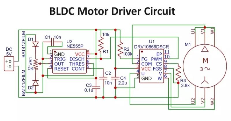
The circuit diagram will include the following connections:
- The 555 Timer configured in astable mode to generate a PWM signal.
- Output of the 555 Timer connected to a driver transistor.
- The driver transistor connected to the BLDC motor to amplify the control signal.
- Feedback from the motor or Hall sensors (optional) to ensure proper timing and rotation control.
List of Required Components
- 555 Timer IC: Used to generate the PWM signal for motor control.
- Transistors (NPN/PNP): Amplifies the current from the 555 Timer to drive the motor.
- Resistors: Controls the timing and frequency of the PWM signal.
- Capacitors: Stabilizes the circuit and helps set the timing for the 555 Timer.
- Diodes: Protects the circuit from back EMF generated by the motor.
- BLDC Motor: The load that will be driven by the circuit.
- Power Supply: Provides the required voltage for both the 555 Timer and the motor.
Explanation of Each Component’s Role in the Circuit
- 555 Timer IC: The heart of the circuit that generates a PWM signal based on the resistor and capacitor configuration.
- Transistors: These act as switches, controlled by the PWM output from the 555 Timer, to supply the necessary current to the motor.
- Resistors/Capacitors: They determine the frequency and duty cycle of the PWM signal, allowing for speed adjustment of the motor.
- Diodes: Protect the transistors and the rest of the circuit from voltage spikes caused by the inductive load (motor).
- BLDC Motor: The motor that is being driven, with its speed controlled by the PWM signal generated by the circuit.
Working Principle of the Circuit
The core of the BLDC motor driver circuit revolves around the 555 Timer IC, which is configured to generate a Pulse Width Modulation (PWM) signal. This PWM signal controls the amount of power delivered to the motor, adjusting its speed accordingly.
Step-by-Step Explanation of How the 555 Timer Controls the BLDC Motor:
- Timer Configuration: The 555 Timer is configured in astable mode, where it continuously oscillates between high and low states, producing a PWM signal at its output. The timing components (resistors and capacitors) connected to the 555 Timer determine the frequency of oscillation.
- PWM Signal Generation: The PWM signal is a square wave where the ratio of the “on” time to the total cycle time (known as the duty cycle) controls the amount of power delivered to the motor. A higher duty cycle delivers more power, increasing the motor’s speed, while a lower duty cycle reduces the speed.
- Transistor Switching: The PWM signal from the 555 Timer is too weak to drive the motor directly, so it is fed into a transistor, which acts as a switch. The transistor amplifies the signal and controls the flow of current to the BLDC motor. When the PWM signal is high, the transistor turns on, allowing current to pass through the motor, and when it’s low, the transistor turns off.
- Driving the Motor: As the PWM signal alternates between high and low states, it controls the current flowing to the BLDC motor, causing it to rotate. The motor’s speed is directly proportional to the duty cycle of the PWM signal.
Description of How the Timer Generates the Required PWM Signal to Drive the Motor:
The 555 Timer in astable mode generates a continuous square wave, which serves as the PWM signal. By adjusting the values of the resistors and capacitors connected to the timer, you can modify the frequency and duty cycle of this signal. The duty cycle represents the percentage of time the signal stays high during each cycle, which corresponds to how much power is sent to the motor. A 50% duty cycle means the signal is on for half the time, providing moderate motor speed, while a 90% duty cycle results in a higher motor speed.
Explanation of Speed Control and How the Duty Cycle Is Adjusted:
Speed control in this circuit is achieved by varying the duty cycle of the PWM signal. This can be done by changing the resistor or capacitor values in the 555 Timer’s configuration. As the duty cycle increases, more power is delivered to the motor, increasing its speed. Conversely, reducing the duty cycle decreases the power supplied, slowing the motor. This method allows for precise control over the motor speed without significant energy loss, making it efficient for many applications.
Advantages of Using 555 Timer for BLDC Motor Control
The 555 Timer offers several key advantages when used in a BLDC motor control circuit, making it a popular choice for simple and cost-effective designs.
Simplicity and Cost-Effectiveness:
- The 555 Timer is widely available and inexpensive, making it an ideal choice for low-cost motor control circuits.
- Its simple design requires few external components (resistors, capacitors, transistors), which reduces the overall cost of the circuit.
Flexibility in PWM Signal Generation:
- The 555 Timer is highly flexible and can be easily configured to generate PWM signals with various frequencies and duty cycles. This flexibility allows for precise control over the motor’s speed and power consumption.
- Adjusting the circuit for different motor specifications or applications is straightforward by tweaking resistor and capacitor values.
Reliability in Motor Control Applications:
- The 555 Timer IC is known for its robustness and reliability in a wide range of environments and applications. Its stable performance ensures consistent motor control even under varying conditions.
- The 555 Timer’s long track record in electronics makes it a trusted component for motor driver circuits, providing dependable operation over time.
Applications of 555 Timer-Based BLDC Motor Driver Circuits
The simplicity and versatility of the 555 Timer IC make it suitable for a wide variety of practical applications involving BLDC motors.
Practical Use Cases of This Circuit in Various Applications:
- RC Cars: The ability to control motor speed with precision makes this circuit ideal for remote-controlled cars, where quick response and smooth operation are essential.
- Drones: BLDC motors are commonly used in drones for their lightweight and efficient performance. A 555 Timer-based driver can control the motors, enabling smooth flight and speed adjustments.
- Fans and Pumps: BLDC motors are frequently used in fans and water pumps for their efficiency and quiet operation. The 555 Timer allows for speed adjustments based on the application’s requirements.
Benefits in Industrial and Consumer Applications:
- Automation: In industrial automation systems, BLDC motors are used for various tasks that require precise motor control. A 555 Timer-based driver can provide cost-effective control without the need for complex microcontrollers.
- Consumer Electronics: Many consumer products, like cooling fans and electric tools, use BLDC motors for their quiet operation and long lifespan. A 555 Timer circuit offers a simple solution for controlling these motors, ensuring consistent performance.
Conclusion
In conclusion, The combination of the 555 Timer IC and a BLDC motor offers a practical and reliable solution for motor control applications. This circuit provides an easy-to-build, cost-effective method to generate PWM signals, giving precise control over motor speed and performance. Its wide range of applications, from consumer electronics to industrial systems, demonstrates the versatility and efficiency of using the 555 Timer in BLDC motor driver circuits. Whether for hobbyist projects or professional implementations, the 555 Timer remains a go-to component for simple motor control.
FAQs
Q1. Can I use the 555 Timer to control the direction of a BLDC motor?
A: No, the 555 Timer only generates the PWM signal for speed control. To change the direction of a BLDC motor, you would need additional components such as an H-bridge circuit or a dedicated BLDC motor controller.
Q2. What is the maximum power the 555 Timer can handle for a BLDC motor?
A: The 555 Timer itself cannot directly handle high power. It can only provide a low-power PWM signal. For driving a BLDC motor, you’ll need a power transistor or MOSFET to handle the high current required by the motor.
Q3. How can I adjust the speed of the motor using the 555 Timer circuit?
A: The motor speed can be adjusted by varying the duty cycle of the PWM signal. This can be done by changing the values of the resistors or capacitors in the 555 Timer’s configuration, which alters the on/off ratio of the PWM signal.
Q4. What are the limitations of using the 555 Timer in motor control circuits?
A: While the 555 Timer is versatile and easy to use, it may not be ideal for very complex motor control systems or high-frequency PWM applications. Additionally, it lacks the precision and features of more advanced microcontroller-based motor controllers.
Q5. Can the 555 Timer be used for both speed control and position control of a BLDC motor?
A: The 555 Timer is best suited for speed control. Position control of a BLDC motor typically requires a more advanced controller with feedback mechanisms, such as encoders or Hall-effect sensors.
