The Role of Schematic diagram in Electronics Industry
Schematic diagrams serve as the backbone of the electronics industry, providing a visual representation of electronic circuits and systems. These diagrams utilize standardized symbols to denote various electronic components, such as resistors, capacitors, transistors and connections between them. By translating complex electronic configurations into simplified visual forms, schematic diagrams facilitate a clearer understanding of circuit designs and functionalities. In this blog we will learn about the Role of Schematic diagram in Electronics Industry. Let’s see the definition of schematic diagram!
What is a Schematic Diagram?
A schematic diagram is a graphical representation that outlines the elements or components of a system and illustrates the relationships and interactions between these parts. These diagrams are indispensable in various fields including electronics, engineering, and architecture, as they offer a simplified and clear view of intricate systems. By abstracting the complexities, schematic diagrams enable professionals to understand, troubleshoot, and communicate the functioning and structure of the system effectively.
The primary purpose of a schematic diagram is to provide a visual blueprint that aids in the design, analysis, and maintenance of systems. For instance, in electronics, a schematic diagram can depict the arrangement of circuits without delving into the physical layout of components. This abstraction helps engineers and technicians focus on the functionality and operation of the system rather than getting bogged down by physical constraints.
Components of a Schematic Diagram
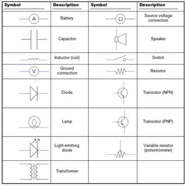
Basic components of a schematic diagram include symbols that represent various system elements, such as resistors, capacitors, switches, and other components in the case of electronic schematics. These symbols are standardized to ensure consistency and understanding across different users and applications. Lines and arrows illustrate the connections and flow of information or signals between these elements, providing a comprehensive overview of how the system operates.
It’s crucial to distinguish between schematic diagrams and other types of diagrams, like block diagrams and flowcharts. While block diagrams offer a broader view by representing major system components as blocks and their interconnections, they lack the detailed specificity of schematic diagrams. Flowcharts, on the other hand, are primarily used to represent step-by-step processes or workflows and are more suited for procedural tasks rather than system structures. Schematic diagrams stand out for their detailed and precise depiction of system components and their interactions, making them a vital tool for professionals across various technical fields.
Types of Schematic Diagrams
Schematic diagrams are essential tools in various fields, providing a visual representation of systems and their components. Among the myriad types, certain schematic diagrams stand out due to their widespread application and specific functionalities. Understanding these types is crucial for professionals across industries, as each serves a unique purpose and offers distinct advantages.
Electrical Schematics
Electrical schematics are detailed representations of electrical systems. They depict how different components such as resistors, capacitors, and switches are interconnected. These diagrams are vital in designing, troubleshooting, and maintaining electrical systems, ensuring safety and efficiency. Electrical schematics are commonly used in manufacturing, automotive, and aerospace industries, where precise electrical configurations are critical.
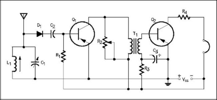
Electronic Circuit Diagrams
Similar to electrical schematics, electronic circuit diagrams focus on electronic components and their connections. These diagrams illustrate the flow of electricity through various elements like transistors, diodes, and integrated circuits. They are indispensable in the development of electronic devices, from simple gadgets to complex computing systems. Engineers and technicians rely on electronic circuit diagrams to innovate, test, and refine electronic products.
Wiring Diagrams
Wiring diagrams provide a more straightforward view of electrical circuits, emphasizing the physical layout of wires and connectors. They are often used in construction and automotive repair to ensure correct installation and maintenance of electrical systems. By showing the actual location of components and connections, wiring diagrams simplify the troubleshooting process, making it easier to identify and fix issues.
Architectural Schematics
Architectural schematics are used in the planning and construction of buildings. These diagrams offer a visual representation of structural elements, electrical systems, plumbing, and HVAC installations. Architects and construction professionals use these schematics to ensure that all aspects of a building are well-coordinated and meet regulatory standards. Architectural schematics play a pivotal role in creating safe, functional, and aesthetically pleasing structures.
Top Free Schematic Drawing Software
Schematic drawing software is indispensable for anyone engaged in designing or understanding circuits and systems. Such tools help visualize complex electronic designs, making it easier to troubleshoot, share, and modify them. Below, we explore some of the best free schematic drawing software available, highlighting their key features, usability, and additional resources to get you started.
KiCad
KiCad is an open-source software suite that offers a comprehensive set of tools for creating schematics and PCB layouts. Its key features include a vast component library, multi-sheet schematics, and a 3D viewer for inspecting PCB designs. KiCad is compatible with Windows, macOS, and Linux, making it accessible to a wide range of users. The software enjoys robust community support, with extensive documentation, tutorials, and forums available to assist beginners and professionals alike.
Fritzing
Fritzing is another popular free tool, particularly favored by hobbyists and educators. It simplifies the process of turning breadboard designs into schematics and PCB layouts. Key features include an intuitive drag-and-drop interface, a broad component library, and the ability to generate production files for PCB manufacturing. Fritzing is available on Windows, macOS, and Linux. The platform also offers a vibrant community and numerous tutorials to help users get started quickly.
EasyEDA
EasyEDA is a web-based schematic and PCB design tool that combines ease of use with powerful features. It allows users to design, simulate, and share their electronic projects entirely online. Key features include a rich component library, real-time collaboration, and integration with PCB fabrication services. EasyEDA is compatible with any operating system with a modern web browser. The tool is supported by extensive documentation, community forums, and video tutorials.
Creating and Reading Schematic Diagrams
Creating a schematic diagram involves several essential steps to ensure clarity and accuracy. The first step is to identify the components that will be included in the diagram. It is crucial to use standard symbols to represent these components, which helps maintain consistency and readability. Common symbols include resistors, capacitors, diodes, and transistors. Refer to a standard schematic symbols chart to ensure correct representation.
The next step is to choose the right tools for drawing the diagram. There are various software options available, both free and paid. Popular free schematic drawing software includes KiCad, Fritzing, and EasyEDA. KiCad offers a comprehensive suite of tools for schematic capture and PCB layout, making it suitable for more complex projects. Fritzing is user-friendly, ideal for beginners, and supports breadboard layouts. EasyEDA provides an online platform for schematic design and simulation, perfect for collaborative projects.
When creating the diagram, it’s essential to label each component clearly. This involves assigning unique identifiers (e.g., R1 for the first resistor) and specifying component values (e.g., 10kΩ for a resistor). Proper labeling ensures that anyone reading the diagram can easily understand it and identify each component without confusion. Additionally, using grid lines can help align components neatly, enhancing the diagram’s overall readability.
Interpreting and reading schematic diagrams require understanding the relationships between components. Focus on the connections between symbols, which represent the flow of current or signals within the circuit. Pay attention to the orientation of components and the direction of current flow, indicated by arrows for diodes or transistors. Tracing the circuit path from the power source through the components to the ground can provide a clearer understanding of the circuit’s function.
Conclusion
In conclusion, while the challenges in creating and interpreting schematic diagrams are considerable, the future holds promising innovations that will enhance the accuracy, efficiency, and capabilities of schematic diagramming. Continuous education and skills development remain crucial for professionals to adapt to these evolving trends and maintain their expertise in this dynamic field.