Silicon Controlled Rectifier (SCR): Construction, Working and Applications
A Silicon Controlled Rectifier (SCR) is a semiconductor device that acts as a switch, rectifier, and voltage regulator. It is widely used in power control applications due to its ability to handle high voltages and currents. The SCR is a type of thyristor, known for its efficiency in converting alternating current (AC) to direct current (DC) and controlling power in various electrical circuits.
SCRs play a crucial role in modern electronics by providing efficient power control and conversion. They are integral in applications such as motor speed controls, light dimmers, pressure control systems, and inverters. Their ability to handle large power loads and switch on and off rapidly makes them invaluable in industrial, commercial, and residential settings.
The purpose of this article is to provide a comprehensive understanding of Silicon Controlled Rectifiers (SCRs). It will cover the definition, construction, working principle, and applications of SCRs, offering detailed insights into their operation and significance. This article aims to serve as a valuable resource for students, engineers, and professionals interested in power electronics.
What is SCR?
A Silicon Controlled Rectifier (SCR) is a four-layer semiconductor device consisting of alternating layers of P-type and N-type materials (PNPN structure). It functions as a switch that can conduct or block current flow, depending on the gate signal. SCRs are controlled by applying a small current to the gate terminal, which allows them to switch from a non-conducting to a conducting state.
Historical Background and Development
The SCR was developed in the late 1950s by a team of engineers at General Electric, including William Shockley, who also co-invented the transistor. The invention of the SCR marked a significant advancement in the field of power electronics, providing a reliable and efficient means of controlling large electrical currents.
Comparison with Other Rectifiers (e.g., Diodes, Triacs)
SCRs differ from diodes in that they can be controlled by a gate signal, whereas diodes can only conduct current in one direction. Unlike triacs, which can control current flow in both directions, SCRs are unidirectional. This makes SCRs particularly suited for applications requiring controlled rectification and power regulation.
Construction of SCR
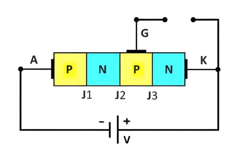
An SCR consists of three main terminals: the anode, cathode, and gate. The anode is the positive terminal, the cathode is the negative terminal, and the gate is the control terminal. The device is constructed using four layers of semiconductor materials arranged in a PNPN structure.
Anode, Cathode, and Gate Terminals
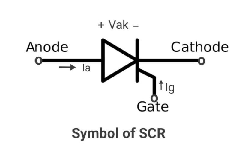
- Anode: Connected to the P-type material at one end of the device.
- Cathode: Connected to the N-type material at the opposite end of the device.
- Gate: Connected to the P-type material near the cathode. It controls the device’s switching.
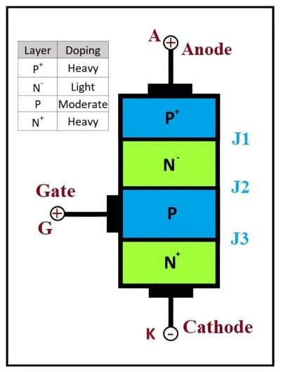
Layers of Semiconductor Materials (PNPN Structure)
The PNPN structure consists of:
- P-type material (Anode)
- N-type material
- P-type material (Gate region)
- N-type material (Cathode)
Each layer is doped to create the necessary electrical characteristics for the SCR to function.
Types of SCR Construction
SCRs can be constructed in different ways to suit various applications. The two main types are:
Planar Type
Planar SCRs are constructed using a planar process where the semiconductor layers are deposited on a flat substrate. This type of construction is common in integrated circuits and is known for its reliability and efficiency.
Mesa Type
Mesa SCRs are constructed by etching the semiconductor layers to form a mesa-like structure. This type of construction allows for better control of the device’s electrical characteristics and is often used in high-power applications.
Diagrams and Illustrations of SCR Construction
Working Principle of SCR
Basic Working Mechanism
The SCR operates by switching between a non-conducting (off) state and a conducting (on) state. When a sufficient gate current is applied, the SCR switches to the conducting state, allowing current to flow from the anode to the cathode.
How SCR Conducts and Blocks Current
In the non-conducting state, the SCR blocks current flow between the anode and cathode. When a gate current is applied, it triggers the SCR to switch to the conducting state, allowing current to pass through.
Role of Gate Signal in Triggering SCR
The gate signal is crucial for triggering the SCR. A small current applied to the gate terminal initiates the conduction process. Once triggered, the SCR remains in the conducting state even if the gate current is removed, provided the current through the SCR stays above the holding current level.
SCR Modes of Operation
Forward Blocking Mode
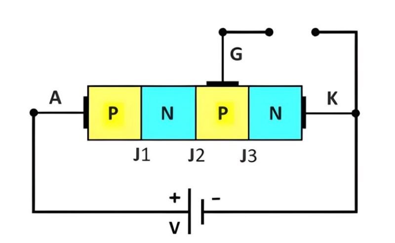
In this mode, the SCR is in the off state, and no current flows from the anode to the cathode despite a forward voltage.
Forward Conduction Mode
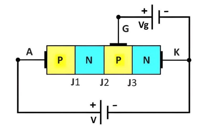
When a gate current is applied, the SCR switches to the on state, allowing current to flow from the anode to the cathode.
Reverse Blocking Mode
In this mode, the SCR blocks current flow from the cathode to the anode when a reverse voltage is applied.
Detailed Explanation of SCR Switching Characteristics
Turn-On Process
The turn-on process occurs when a sufficient gate current is applied, causing the SCR to switch from the forward blocking mode to the forward conduction mode.
Turn-Off Process
The turn-off process occurs when the current through the SCR drops below the holding current level, causing the SCR to switch back to the forward blocking mode.
Latching Current and Holding Current
- Latching Current: The minimum current required to maintain the SCR in the conducting state immediately after it has been triggered.
- Holding Current: The minimum current required to keep the SCR in the conducting state once it has been latched.
Applications of SCR
Overview of SCR Applications in Various Fields
Silicon Controlled Rectifiers (SCRs) are versatile devices used in numerous applications across various fields. Their ability to handle high power and control large currents makes them essential in both industrial and consumer electronic applications. SCRs are employed in power control, power conversion, and various other functions that require reliable and efficient electronic switching.
Industrial Applications
In industrial settings, SCRs are critical for controlling high-power equipment and machinery. They are used in processes that require precise control over power flow, such as in the operation of electric furnaces, welding machines, and industrial heaters. SCRs are also used in motor control systems, enabling efficient regulation of motor speed and torque.
Consumer Electronics
SCRs are found in many consumer electronics, providing efficient power control and regulation. They are used in household appliances such as washing machines, where they control the motor speed, and in light dimmers, where they adjust the brightness of lighting fixtures.
Power Control and Conversion
SCRs are extensively used in power control and conversion applications. They are key components in rectifiers that convert AC to DC, inverters that convert DC to AC, and in voltage regulators that maintain a stable output voltage. Their ability to switch high voltages and currents makes them ideal for use in power supplies and conversion systems.
Specific Examples of SCR Applications
Motor Speed Control
SCRs are used to control the speed of electric motors by adjusting the power supplied to the motor. This is particularly useful in applications requiring variable speed control, such as conveyor belts, fans, and pumps.
Light Dimmers
In lighting applications, SCRs allow for the adjustment of light intensity. By controlling the phase of the AC power supply, SCRs can dim lights smoothly and efficiently.
Power Regulators
SCRs are used in power regulation systems to maintain a constant output voltage. They regulate the power flow to ensure that electronic devices receive a stable voltage, protecting them from power fluctuations.
Controlled Rectifiers
SCRs are essential in controlled rectifier circuits, which convert AC to DC with adjustable output. These circuits are used in power supplies for various electronic devices and systems.
Advantages and Limitations of Using SCR
Advantages:
- High efficiency in controlling large power loads
- Ability to handle high voltages and currents
- Reliable and durable with a long operational life
- Fast switching capabilities
Limitations:
- Requires a gate current to trigger
- Once triggered, it cannot be turned off by the gate signal alone
- Sensitive to overcurrent and overvoltage conditions
- Requires protective measures to ensure reliable operation
Protection and Reliability of SCR
Common Issues and Failures in SCR Operation
SCRs can experience several issues and failures during operation, primarily due to excessive current, voltage, or heat.
- Overcurrent: Excessive current can damage the SCR by causing excessive heating and potentially leading to thermal runaway.
- Overvoltage: High voltage spikes can cause the SCR to breakdown, leading to permanent damage.
- Thermal Runaway: If the SCR is not adequately cooled, it can overheat, leading to a self-reinforcing cycle of increasing temperature and current, eventually resulting in failure.
Methods of Protecting SCR
Snubber Circuits
Snubber circuits protect SCRs from voltage spikes by absorbing and dissipating excess energy, thus preventing overvoltage conditions.
Fuses and Circuit Breakers
Fuses and circuit breakers provide overcurrent protection by disconnecting the power supply when current exceeds a safe threshold.
Heat Sinks and Cooling Mechanisms
Heat sinks and cooling mechanisms are essential for dissipating heat generated by the SCR during operation, preventing thermal runaway and ensuring reliable performance.
Tips for Ensuring Reliable Operation of SCR
- Ensure adequate cooling and ventilation to prevent overheating
- Use snubber circuits to protect against voltage spikes
- Implement fuses and circuit breakers for overcurrent protection
- Regularly inspect and maintain the SCR and associated circuits to ensure proper operation
Conclusion
This article provided an in-depth look at Silicon Controlled Rectifiers (SCRs), covering their construction, working principles, and applications. SCRs are critical components in power electronics, capable of handling high voltages and currents and providing efficient power control.
The future of SCR technology looks promising, with ongoing research and development aimed at improving their efficiency, reliability, and integration into more advanced electronic systems. Advancements in materials and manufacturing techniques will likely lead to even more robust and versatile SCRs, further expanding their applications and capabilities.