OP AMP Integrator Circuit
An operational amplifier (op-amp) integrator circuit is a fundamental analog circuit that performs the mathematical operation of integration. This means it produces an output signal that is proportional to the integral of the input signal. In simpler terms, an integrator sums up the input signal over time, making it a crucial component in various analog computing tasks, signal processing, and waveform generation applications.
Ideal Op Amp Integrator Circuit
The ideal op-amp integrator circuit consists of an operational amplifier with a feedback capacitor connected between its output and inverting input, and the input signal is applied through a resistor to the inverting input. The non-inverting input of the op-amp is grounded. In this configuration, the output voltage (Vout) is the time integral of the input voltage (Vin).
Expression for the Output Voltage
For an ideal op-amp integrator, the output voltage can be mathematically expressed as:
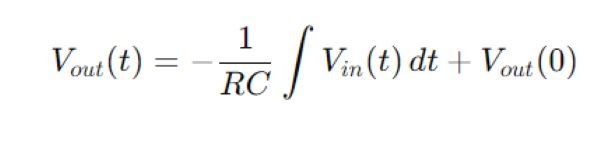
where:
- R is the resistance connected to the inverting input,
- C is the capacitance in the feedback loop,
- Vin(t) is the input voltage as a function of time,
- Vout(0) is the initial output voltage at time t=0.
This equation shows that the output voltage is proportional to the negative integral of the input voltage over time.
Practical OP-AMP Integrator Circuit
In a real-world scenario, an ideal op-amp integrator is rarely used due to its limitations, such as drift and instability caused by the absence of a DC path for the input bias current. To mitigate these issues, a practical op-amp integrator circuit includes a resistor in parallel with the feedback capacitor. This resistor helps stabilize the circuit by providing a DC path, which prevents the op-amp from saturating and ensures accurate integration over time.
Op-Amp Integrator as Ramp Signal Generator
When a constant DC input is applied to an op-amp integrator, the output is a linear ramp signal. This occurs because the integral of a constant is a linear function of time. The slope of the ramp is determined by the input voltage and the RC time constant of the circuit. This property is useful in applications such as waveform generators, where a linear ramp signal is needed.
Output for a Sinewave Input Signal
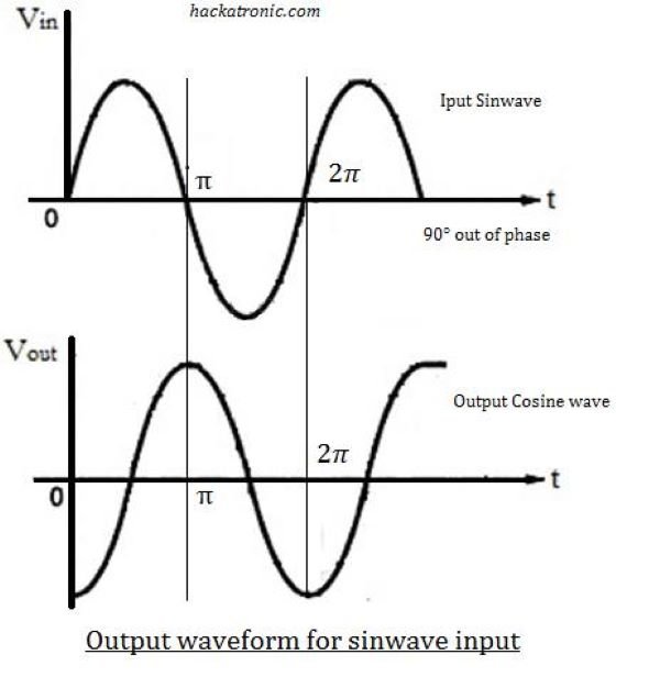
When a sinewave input signal is applied to an op-amp integrator, the output signal will be a cosine waveform, which is the integral of a sine function. The amplitude and phase of the output waveform are dependent on the frequency of the input sinewave and the RC time constant. Specifically, the output will have a 90-degree phase shift relative to the input signal and an amplitude that is inversely proportional to the input frequency.
Advantages of Op Amp Integrator
- High Accuracy: The op-amp integrator provides precise integration, especially in ideal conditions.
- Versatile Applications: It is widely used in analog computers, waveform generation, and signal processing.
- Simple Design: The circuit is relatively simple to design and implement using basic components.
Disadvantages of Op-Amp Integrator
- Sensitivity to DC Offsets: The output can drift due to small DC offsets, leading to inaccuracies.
- Limited Frequency Response: Practical integrators have a limited frequency range due to the presence of a parallel resistor.
- Potential for Instability: Without proper design, the circuit can become unstable or saturate over time.
Applications of an OP AMP Integrator
- Analog Computers: Used for performing integration operations in analog computing.
- Waveform Generators: Generates ramp or triangular waveforms for various applications.
- Signal Processing: Useful in filtering applications, such as in low-pass filters.
- Control Systems: Used in control systems to integrate error signals over time.
Conclusion
The op-amp integrator circuit is a versatile and essential component in analog electronics, capable of performing accurate integration of input signals. While the ideal integrator offers high precision, practical implementations must address real-world limitations like drift and instability. Despite its drawbacks, the op-amp integrator remains widely used in various applications, from signal processing to waveform generation.