How to Make an LED Chaser Circuit Using 555 Timer IC and CD4017 Counter IC
An LED chaser circuit is a fascinating and straightforward electronic project that creates a dynamic visual effect by sequentially lighting up a series of LEDs. This project is popular among hobbyists and electronics enthusiasts due to its ease of construction and flexibility in creating various lighting effects. The circuit’s heart lies in the use of a 555 Timer IC and a CD4017 decade counter IC, which together generate and control the sequence of pulses required to light up the LEDs in a chasing pattern. Beyond its entertainment value, this project provides an excellent introduction to basic electronics concepts and circuit design.
Basic Components of an LED Chaser Circuit
To build an LED chaser circuit, several essential components are required. Each plays a specific role in achieving the desired chasing effect.
Power Supply: Role and Specifications
The power supply provides the necessary voltage to operate the circuit. A 5V DC power source is commonly used for its compatibility with the ICs and LEDs. A battery or a regulated power supply can be used to ensure stable and consistent operation.
Timer IC: Explanation of Pulse Generation and Sequencing Control
The 555 Timer IC is configured as an astable oscillator in this circuit. It generates a continuous series of pulses at a specific frequency, which determines the speed of the LED chasing effect. By adjusting the values of resistors and capacitors connected to the 555 Timer, the frequency of these pulses can be modified, allowing for precise control over the effect.
LEDs: Use in Creating the Chasing Effect
Light Emitting Diodes (LEDs) are the core visual element of the circuit. A series of LEDs is arranged in a sequence, and they illuminate one after another in a chasing pattern. The choice of LED colors, arrangement, and quantity can be customized to create different visual effects.
Resistors: Purpose in Current Limitation
Resistors are used to limit the current flowing through the LEDs, preventing them from drawing excessive current that could cause damage. Each LED typically has a corresponding resistor, chosen based on the LED’s forward voltage and the circuit’s supply voltage.
Additional Components: Diodes, Capacitors, Transistors, and Their Optional Roles
- Diodes: Used for rectification or protection to prevent reverse current flow.
- Capacitors: Help in stabilizing the power supply and controlling the timing in the 555 Timer circuit.
- Transistors: Act as switches to amplify the current, ensuring proper operation of LEDs when higher power is required.
- Potentiometers: Provide adjustable resistance to fine-tune the circuit’s behavior.
Components Required
To construct the LED chaser circuit, the following components are necessary:
- 555 Timer IC: Functions as an astable oscillator to generate pulses.
- CD4017 Decade Counter IC: Manages the sequencing of LEDs.
- LEDs: 10 red LEDs (or other colors as desired).
- Resistors:
- 1MΩ for setting pulse timing.
- 10kΩ for the reset pin of the 555 Timer.
- 220Ω for limiting current through LEDs.
- 50kΩ Potentiometer: Allows for adjustable frequency control.
- Capacitors:
- 0.22µF for timing.
- 10nF for stability.
- Jumper Wires: For connections between components.
- Breadboard or PCB: To assemble the circuit.
- Power Supply: A 5V battery or regulated power source.
Circuit Design and Assembly
Schematic Overview
The LED chaser circuit consists of a 555 Timer IC configured in astable mode to generate pulses, which are fed into the clock input of the CD4017 decade counter IC. The CD4017 sequentially activates its output pins based on the incoming pulses, lighting up the connected LEDs one after another. Resistors, capacitors, and a potentiometer are used to adjust the timing and current in the circuit.
PCB Design
- Plan the Layout: Begin by arranging the components in a logical layout, ensuring minimal crossover of connections.
- Design the PCB: Use software like KiCAD or Eagle to create the schematic and PCB layout. For aesthetic purposes, consider a circular PCB design to represent a running light pattern.
- Etch and Drill: Transfer the design to a copper-clad board, etch the unwanted copper, and drill holes for the components.
Circuit Assembly
- Place the components on a breadboard or PCB as per the schematic.
- Connect the 555 Timer IC, CD4017 IC, LEDs, resistors, capacitors, and the power supply.
- Use jumper wires for connections and verify all connections against the schematic.
- Test the circuit by powering it on and observing the chasing LED effect.
Working Principle
555 Timer IC as an Astable Oscillator
The 555 Timer is set up in an astable configuration, producing a continuous stream of square wave pulses. These pulses act as clock signals for the CD4017 IC.
Pulse Frequency Adjustment
The frequency of the 555 Timer’s output is determined by the values of the resistors and capacitor connected to it. The 50kΩ potentiometer allows for dynamic frequency adjustments, enabling control over the speed of the LED sequence.
Role of CD4017 Decade Counter IC
The CD4017 IC receives the clock pulses from the 555 Timer and sequentially activates its output pins. Each activated output drives an LED, creating the chasing effect.
Cascading Effect and LED Interaction
The LEDs light up in sequence, as each pin of the CD4017 IC is activated in order. Transistors may be used to amplify the current, ensuring that each LED receives sufficient power without overloading the IC.
Adjusting Speed and Effects
By varying the resistance of the potentiometer or changing the values of the resistors and capacitor in the 555 Timer circuit, the pulse frequency can be increased or decreased. This directly affects the speed of the chasing effect, allowing for customization based on user preference.
Applications and Modifications
Common Applications
LED chaser circuits are versatile and can be used in various applications, including:
- Decorative Lighting: Ideal for holiday decorations, party lights, and other aesthetic purposes.
- Automotive Lighting: Used in car indicators, running lights, and dashboard designs.
- Safety Lighting: Useful in alert systems and attention-grabbing signals.
Creative Modifications
- Using Different LED Colors: Incorporating RGB LEDs can create a colorful and dynamic chasing effect, adding vibrancy to the design.
- Adding More Chains of Transistors: Increasing the number of transistor chains allows for more complex patterns and longer sequences of LEDs.
- Custom LED Arrangements: Experimenting with unique patterns, such as circular, triangular, or spiral layouts, to enhance the visual appeal.
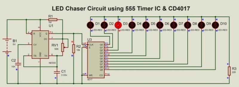
LED Chaser Circuit Diagram
The circuit diagram shows the connection between the 555 Timer IC, CD4017 Decade Counter IC, resistors, capacitors, and LEDs. The 555 Timer serves as the pulse generator, while the CD4017 directs the sequencing of the LEDs.

Key Connections and Design Choices
- 555 Timer IC: Configured in astable mode with resistors and a capacitor to set the oscillation frequency.
- CD4017 IC: Clock input connected to the 555 Timer output, and sequential outputs driving the LEDs.
- LEDs: Each LED connected to a resistor to limit current and prevent damage.
- Power Supply: A 5V source powers the circuit, ensuring compatibility with all components.
PCB Design for LED Chaser
A circular PCB layout can be used to create an appealing running light pattern. The LEDs are arranged in a circular formation, and the connections follow the schematic.

Steps to Prepare and Assemble the PCB
- Design the PCB: Use software to map out the connections, ensuring a clean and organized layout.
- Etch the Board: Transfer the design onto a copper-clad board, etch away the excess copper, and drill component holes.
- Assemble the Components: Solder the 555 Timer, CD4017, resistors, capacitors, LEDs, and other components onto the PCB.
- Test the Circuit: Connect the power supply and observe the LEDs to verify correct operation.
Conclusion
In conclusion, The LED chaser circuit is an excellent project for beginners and hobbyists, offering a hands-on experience in electronics and circuit design. By understanding the roles of the 555 Timer and CD4017 IC, users can create dynamic and visually appealing lighting effects. With its wide range of applications and potential for creative modifications, this project provides a rewarding opportunity to explore and learn. Experimenting with different designs and configurations can lead to unique and exciting results, making the LED chaser circuit a staple in DIY electronics.