Difference between Coupling, Decoupling and Bypass Capacitors
Capacitors are fundamental components in electronic circuits, serving a variety of functions that are crucial for the proper operation of devices. Among these functions, coupling, decoupling, and bypassing are key roles that capacitors play in ensuring signal integrity, noise reduction, and stable operation of circuits. Although these capacitors might seem similar at a glance, they serve different purposes in various applications. Understanding the differences between coupling, decoupling, and bypass capacitors is essential for designing efficient and reliable electronic systems. In this article, we will explore these types of capacitors, their specific roles in circuits, and how they differ from one another.
Coupling Capacitors
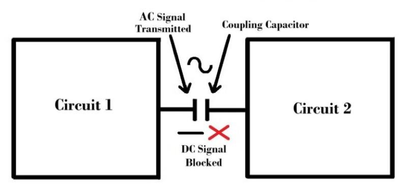
Coupling capacitors, also known as DC-blocking capacitors, are used to transmit AC signals between different stages of a circuit while blocking DC components. This allows for the isolation of different DC bias points in different sections of a circuit. They are usually placed between two active stages (like transistor or op-amp stages) to ensure that the DC biasing of one stage does not affect the subsequent stage.
Applications:
- Signal Transmission: Coupling capacitors are commonly used in amplifiers to couple audio or RF signals between different stages without allowing DC to pass through.
- AC Coupling: In audio equipment, coupling capacitors ensure that only the AC part of the signal (like audio) is transmitted from one stage to another, preventing any DC offset from being passed along.
- RF Circuits: Used in radio frequency (RF) circuits to block DC while allowing high-frequency signals to pass.
Decoupling Capacitors
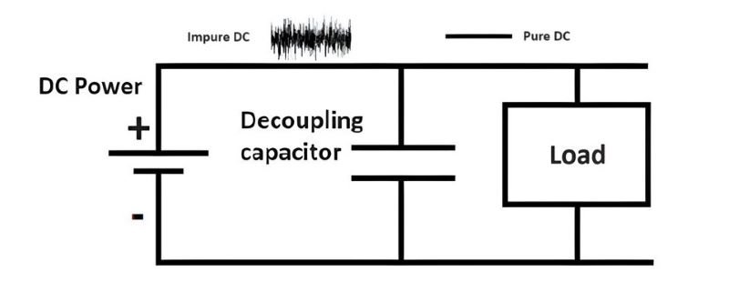
Decoupling capacitors, also known as bypass capacitors, are used to filter out noise or unwanted AC signals from the power supply, ensuring that each component in the circuit receives a stable DC voltage. They are typically placed near the power supply pins of active devices like microcontrollers, ICs, and transistors to smooth out voltage spikes and suppress high-frequency noise.
Applications:
- Power Supply Stabilization: In digital circuits, decoupling capacitors stabilize the power supply voltage by absorbing voltage spikes caused by switching transients.
- Noise Reduction: Decoupling capacitors help reduce electromagnetic interference (EMI) and radio-frequency interference (RFI) by shunting high-frequency noise to the ground.
- Digital Circuits: Used in microcontroller circuits, where rapid switching can cause voltage fluctuations, leading to instability. Decoupling capacitors provide a local reservoir of charge to maintain stable voltage.
Bypass Capacitors

Bypass capacitors are used to provide a low impedance path to ground for high-frequency noise, effectively bypassing the noise away from the critical components in the circuit. They are similar to decoupling capacitors but are more specifically focused on shunting noise directly to ground, ensuring that it doesn’t affect the operation of sensitive components.
Applications:
- High-Frequency Noise Suppression: In analog circuits, bypass capacitors are used to shunt high-frequency noise to ground, preventing it from interfering with the operation of amplifiers or other sensitive components.
- Power Supply Filtering: Often used in conjunction with decoupling capacitors to ensure that both high and low-frequency noise are adequately filtered from the power supply lines.
- RF Circuits: Bypass capacitors are critical in RF circuits where they help maintain signal integrity by preventing noise from affecting the circuit’s performance.
Key Differences
While coupling, decoupling, and bypass capacitors all involve the use of capacitors to manage signal and noise, they each serve distinct functions within a circuit. Here, we delve into the specific differences between these capacitors:
Coupling Capacitors:
- Purpose: Block DC while allowing AC signals to pass between circuit stages.
- Placement: Typically placed between stages of amplifiers or other signal processing circuits.
- Function: Ensures that DC biasing in one stage doesn’t affect subsequent stages while transmitting AC signals.
Decoupling Capacitors:
- Purpose: Stabilize the power supply voltage by filtering out noise and voltage spikes.
- Placement: Located close to power supply pins of ICs, microcontrollers, or transistors.
- Function: Provides a local reservoir of charge to maintain stable voltage and suppress noise.
Bypass Capacitors:
- Purpose: Shunt high-frequency noise directly to ground, bypassing it from critical circuit paths.
- Placement: Positioned between power supply lines and ground, often near sensitive components.
- Function: Filters out high-frequency noise, ensuring it doesn’t interfere with the operation of the circuit.
Coupling, Decoupling and Bypass Capacitors Difference
| Aspect | Coupling Capacitors | Decoupling Capacitors | Bypass Capacitors |
|---|---|---|---|
| Primary Function | Transmit AC signals while blocking DC components | Stabilize power supply voltage, filter noise | Shunt high-frequency noise to ground |
| Placement | Between circuit stages | Near power supply pins | Between power supply and ground, near components |
| Purpose | Signal transmission and isolation | Power supply stabilization | High-frequency noise suppression |
| Common Applications | Audio and RF circuits, amplifier stages | Digital circuits, microcontrollers | Analog circuits, RF circuits |
Conclusion
Coupling, decoupling, and bypass capacitors each play critical roles in electronic circuits, ensuring that signals are transmitted cleanly, power supplies are stable, and noise is minimized. While their functions may overlap in some aspects, understanding their specific applications and differences is crucial for anyone involved in electronics design. By choosing the right type of capacitor for each application, designers can enhance the performance and reliability of their circuits, leading to more robust and efficient electronic systems.