
Current Switching Circuit using Arduino
Introduction
Current switching circuits are fundamental in controlling the flow of electrical current within a system. These circuits act as switches, allowing or interrupting the current flow based on specific conditions or control signals. They are commonly used in applications where controlling high-power devices, like motors, lights, or heaters, is necessary without directly handling high current at the control level.
The importance of current switching circuits lies in their ability to manage power efficiently and safely. They are crucial in automated systems, power regulation, and protection circuits. Common applications include motor control in industrial machinery, lighting control systems, and power management in various electronic devices. By allowing precise control over the flow of current, these circuits contribute to energy savings and enhanced system performance.
Introduction to the Use of Arduino in Current Switching Circuits
Arduino, a versatile microcontroller platform, simplifies the design and implementation of current switching circuits. With its easy-to-program environment and wide range of compatible components, Arduino enables users to control switching mechanisms with precision. By integrating Arduino into current switching circuits, one can create automated, programmable systems that respond to specific conditions, such as sensor inputs, timers, or user commands.
Components Required
List of Components Needed for the Circuit
- Arduino Board (e.g., Arduino Uno)
- Transistor (e.g., NPN transistor like 2N2222)
- Relay Module
- Diode (e.g., 1N4007)
- Resistor (e.g., 1kΩ)
- Power Supply (e.g., 5V/12V depending on the relay)
- Load (e.g., a motor, LED, or any other high-current device)
Brief Description of Each Component’s Role in the Circuit
- Arduino Board: Acts as the brain of the circuit, providing the necessary control signals to switch the current on and off.
- Transistor: Works as a switch that is controlled by the Arduino to activate or deactivate the relay.
- Relay Module: Electrically isolates the Arduino from the high-current load and allows the control of high-power devices with a low-power signal.
- Diode: Protects the circuit from back EMF generated when the relay coil is de-energized.
- Resistor: Limits the current flowing into the transistor’s base, ensuring safe operation.
- Power Supply: Provides the necessary power for the relay and the load.
- Load: The device being controlled by the current switching circuit.
Circuit Diagram
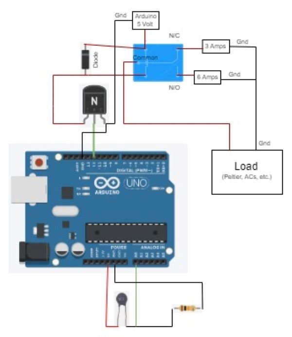
The circuit consists of an Arduino connected to the base of an NPN transistor through a current-limiting resistor. The collector of the transistor is connected to one side of the relay coil, with the other side connected to the positive power supply. A diode is placed across the relay coil to prevent back EMF from damaging the circuit. The emitter of the transistor is connected to the ground. The load, such as a motor or LED, is connected to the relay’s normally open (NO) terminal, with the other terminal connected to the power supply.
Explanation of the Connections Between Components
- The Arduino pin is connected to the base of the transistor through a resistor, allowing the Arduino to control the transistor.
- The transistor acts as a switch, controlling the current flow through the relay coil.
- The relay, when activated by the transistor, closes its contacts, allowing current to flow to the load.
- The diode across the relay coil prevents voltage spikes caused by the relay switching from damaging the transistor or Arduino.
- The load is connected to the relay, which controls the current flow based on the Arduino’s input.
Working Principle
When the Arduino outputs a high signal to the base of the transistor, the transistor turns on, allowing current to flow from the collector to the emitter. This current flow energizes the relay coil, causing the relay contacts to close. When the relay contacts close, the circuit to the load is completed, allowing current to flow through the load.
How the Arduino Controls the Switching Mechanism
The Arduino controls the switching mechanism by sending a digital high or low signal to the base of the transistor. When the signal is high, the transistor switches on, activating the relay and allowing current to flow to the load. When the signal is low, the transistor switches off, deactivating the relay and cutting off the current flow to the load.
Flow of Current and the Role of Different Components During the Switching Process
- Current Flow with High Signal: When the Arduino sends a high signal, the current flows through the transistor, energizing the relay coil. The relay then closes its contacts, allowing current to flow through the load, powering it.
- Role of the Transistor: The transistor acts as a low-power switch that controls the high-current relay.
- Role of the Relay: The relay isolates the low-power control circuit from the high-power load, allowing safe switching of high currents.
- Role of the Diode: The diode protects the circuit from potential damage caused by voltage spikes when the relay is turned off.
This process allows the Arduino to safely and effectively control high-current devices using a low-power signal, making it an essential tool in automated systems and electronic projects.
Arduino Code
// Define the pin connected to the transistor base
const int switchPin = 7; // Digital pin 7

void setup() {
// Initialize the pin as an output
pinMode(switchPin, OUTPUT);
}

void loop() {
// Turn the relay on
digitalWrite(switchPin, HIGH);
delay(1000); // Wait for 1 second

// Turn the relay off
digitalWrite(switchPin, LOW);
delay(1000); // Wait for 1 second
}
Step-by-Step Explanation of the Code, Including Key Functions and Logic
- Pin Definition:
- The code begins by defining
switchPinas the digital pin connected to the base of the transistor. This pin will be used to control the switching mechanism.
- The code begins by defining
- Setup Function:
- In the
setup()function, thepinMode()function is used to setswitchPinas an output. This is essential as this pin will send signals to the transistor to control the relay.
- In the
- Loop Function:
- The
loop()function contains the core logic for controlling the relay. ThedigitalWrite()function is used to send a HIGH signal toswitchPin, which turns the transistor on and activates the relay. Thedelay(1000)function introduces a 1-second pause. - Next, the
digitalWrite()function sends a LOW signal toswitchPin, turning off the transistor and deactivating the relay. Another 1-second pause follows. - This loop continues indefinitely, causing the relay to switch on and off every second.
- The
How to Upload the Code to the Arduino and Test the Circuit
- Connecting the Arduino:
- Connect your Arduino board to your computer using a USB cable.
- Open the Arduino IDE:
- Open the Arduino IDE software on your computer. Copy and paste the provided code into a new sketch.
- Select the Board and Port:
- Go to the
Toolsmenu, select the appropriate Arduino board (e.g., Arduino Uno), and choose the correct COM port.
- Go to the
- Upload the Code:
- Click the Upload button (right arrow) in the Arduino IDE to compile and upload the code to the Arduino board.
- Testing the Circuit:
- Once the code is uploaded, the Arduino will begin executing it. Observe the relay switching on and off every second, which indicates that the current is being controlled as expected. Connect a load, such as an LED or motor, to the relay to see the circuit in action.
Applications
The current switching circuit using Arduino can be applied in various practical scenarios, particularly in automated and controlled environments. It is useful in situations where precise control over high-current devices is required.
Examples of Where and How This Circuit Can Be Used in Real-World Scenarios
- Home Automation: The circuit can be used to control household appliances like lights, fans, or heaters, turning them on or off based on a schedule or sensor input.
- Industrial Automation: In industrial settings, the circuit can control motors, conveyor belts, or other machinery, allowing for automated production processes.
- Robotics: The circuit can be integrated into robotic systems to control actuators, motors, or other components that require high current.
- Power Management Systems: This circuit can be used in power management to control the distribution of power to different parts of a system, ensuring efficient energy use.
Advantages and Limitations
Advantages of Using Arduino for Current Switching
- Ease of Programming: Arduino provides a user-friendly environment for programming, making it accessible even for beginners.
- Flexibility: The Arduino platform allows for easy modification and expansion of the circuit, enabling more complex control systems.
- Cost-Effective: Using an Arduino for current switching is relatively inexpensive compared to other microcontroller platforms.
- Wide Community Support: Arduino has a large and active community, offering a wealth of resources, tutorials, and troubleshooting help.
Potential Limitations or Challenges in Implementing the Circuit
- Limited Current Handling: The transistor and relay used in the circuit may limit the maximum current that can be switched, requiring careful selection of components for high-current applications.
- Response Time: The switching speed may be limited by the relay, making the circuit less suitable for high-speed applications.
- Complexity in Scaling: While Arduino is excellent for small-scale projects, scaling the circuit for more complex or larger applications might require additional components and considerations.
- Reliability: Mechanical relays, while effective, have a limited lifespan compared to solid-state components, potentially affecting long-term reliability.
Conclusion
This article has provided a comprehensive guide to building a current switching circuit using Arduino. It covered the basics of current switching circuits, the components required, the working principle, and practical applications. Additionally, the article presented the Arduino code needed to control the circuit and discussed the advantages and limitations of using Arduino for this purpose.
The current switching circuit using Arduino is an effective solution for controlling high-current devices in various applications. Its ease of use, flexibility, and cost-effectiveness make it a popular choice for both hobbyists and professionals. By leveraging Arduino’s capabilities, users can create automated systems that are both powerful and versatile.
Suggestions for Further Enhancements or Modifications
To enhance the circuit further, consider the following modifications:
- Using Solid-State Relays: For faster switching and increased reliability, solid-state relays can be used instead of mechanical relays.
- Adding Sensors: Integrating sensors like temperature, light, or motion sensors can allow the circuit to respond to environmental conditions automatically.
- Expanding Control: Multiple relays can be controlled simultaneously using additional Arduino pins, allowing for more complex systems.
- Implementing Feedback Mechanisms: Adding feedback mechanisms to monitor current or voltage levels can improve safety and efficiency in the circuit.
These enhancements can make the circuit even more versatile and suitable for a broader range of applications.