Step Up Voltage: A DIY 12V to 24V Voltage Doubler Guide
A voltage doubler is a circuit that increases an input voltage to approximately double its original value. Such circuits are particularly useful in applications where a higher voltage is required, but a higher voltage source is not available. The 555 timer IC, a versatile and widely used component in electronics, plays an imp. role in this circuit by generating precise pulses that drive the voltage doubling process. In this article, we will explore how to design and build a simple and efficient 12V to 24V voltage doubler circuit using a 555 timer IC.
Components Required
Here are the List of Components, which are required:
- 555 Timer IC – Acts as the pulse generator.
- Capacitors:
- 10 µF, 50V electrolytic capacitors (2 units) for charge storage.
- 0.1 µF ceramic capacitor for decoupling.
- Diodes:
- 1N4007 (2 units) for rectification and charge transfer.
- Resistors:
- 10 kΩ (1 unit) for timing control.
- 1 kΩ (1 unit) for current limiting.
- Potentiometer:
- 10 kΩ for adjusting the pulse frequency.
- Breadboard or PCB: For assembling the circuit.
- Power Supply: 12V DC input source.
- Connecting Wires: For wiring the components.
Tools Required
- Soldering iron and solder wire (if using PCB).
- Wire cutters and strippers.
- Multimeter for testing connections and measuring output.
- Oscilloscope (optional) for analyzing the waveform.
Working Principle of Voltage Doubler
A voltage doubler uses capacitors and diodes to increase the voltage level from an input source. The 555 timer generates periodic pulses, which alternately charge and discharge the capacitors. These charge-discharge cycles, facilitated by diodes, effectively transfer charge in such a way that the output voltage becomes approximately double the input voltage.
Theoretical Basis
- 555 Timer Pulse Generation:
- The timer operates in astable mode, generating square wave pulses.
- These pulses create alternating charge and discharge cycles.
- Role of Capacitors and Diodes:
- Capacitors store and release charge during each pulse cycle.
- Diodes direct the charge flow, ensuring that the capacitors discharge in a controlled manner, contributing to the voltage doubling effect.
Circuit Diagram
Here are the well-labeled diagram showing the 555 timer, capacitors, diodes, and their connections.
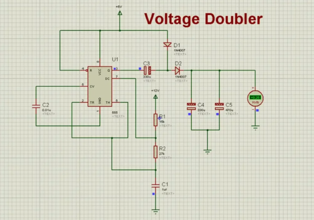
Explanation
- 555 Timer Section:
- Configured in astable mode to generate continuous pulses.
- Resistors and a potentiometer control the frequency of the pulses.
- Voltage Doubling Section:
- Capacitors and diodes form a charge pump circuit.
- The first capacitor stores the initial charge, while the second capacitor adds this charge to the supply voltage during the discharge cycle.
Step-by-Step Circuit Construction
- Prepare the Components:
- Collect all components and tools.
- Test the 555 timer IC and other critical components using a multimeter.
- Assemble the Timer Section:
- Place the 555 timer on a breadboard or solder it onto the PCB.
- Connect resistors, the potentiometer, and the decoupling capacitor to configure the IC in astable mode.
- Connect the Voltage Doubler Section:
- Add the capacitors and diodes in the charge pump configuration.
- Ensure correct polarity for capacitors and diodes to prevent damage.
- Wire the Power Supply:
- Attach the 12V input to the circuit.
- Use proper wire gauges to handle the expected current.
- Verify the Connections:
- Double-check all connections against the circuit diagram.
- Use a multimeter to test for short circuits or incorrect connections.
- Test the Circuit:
- Power on the circuit and measure the output voltage with a multimeter.
- Adjust the potentiometer if necessary to optimize the frequency for stable operation.
Tips for Assembly
- Keep the leads of capacitors and resistors as short as possible to reduce noise.
- Avoid loose connections by soldering all joints firmly if using a PCB.
- Use a breadboard for prototyping to easily make adjustments before finalizing the design.
Working of the Circuit
The circuit operates as a voltage doubler by leveraging the combination of the 555 timer and a charge pump consisting of capacitors and diodes. The 555 timer is configured in astable mode to generate continuous square wave pulses. These pulses alternate between high and low states, driving the charge and discharge cycles of the capacitors. The diodes ensure unidirectional current flow, facilitating the transfer of charge to achieve a voltage doubling effect at the output.
Role of the 555 Timer
- The 555 timer serves as the pulse generator, creating a steady train of square waves.
- The frequency of the pulses is determined by the resistors and the potentiometer connected to the timer.
- These pulses act as a clock signal, synchronizing the charging and discharging of the capacitors.
How Capacitors and Diodes Contribute
- Capacitors: Store and release charge alternately, creating the stepped-up voltage.
- Diodes: Prevent backflow of current and direct the charge flow to combine the input voltage with the stored charge.
Testing and Verification
Methods to Test the Circuit
- Initial Checks:
- Ensure the connections match the circuit diagram.
- Use a multimeter to check for continuity and absence of short circuits.
- Power-On Test:
- Supply 12V DC to the circuit and measure the output voltage.
- Use an oscilloscope to verify the waveform generated by the 555 timer.
- Output Verification:
- Check the output voltage with a multimeter. It should be approximately 24V if the circuit operates correctly.
Troubleshooting Common Issues
- No Output Voltage: Check for loose connections or incorrect component orientation (e.g., diodes and capacitors).
- Low Output Voltage: Verify the frequency of the 555 timer pulses and adjust the potentiometer if needed.
- Instability: Ensure the power supply is stable and decoupling capacitors are properly connected.
Applications
- Powering 24V devices from a 12V source, such as in automotive or portable electronics.
- Boosting voltage for low-power devices like LED strips or sensors.
- Educational projects demonstrating the working of a voltage doubler.
Advantages and Limitations
Advantages
- Simple and cost-effective design.
- Uses readily available components.
- Suitable for low-current applications.
Limitations
- Limited to low-power applications due to capacitor and diode constraints.
- Efficiency decreases with increased current demand.
- Voltage doubling performance depends on the quality of components used.
Conclusion
In conclusion, The 12V to 24V voltage doubler circuit using a 555 timer IC is a practical and efficient solution for applications requiring a stepped-up voltage. By combining the timer’s pulse generation capabilities with the charge pump mechanism of capacitors and diodes, this circuit achieves a reliable voltage boost with minimal components. It serves as a great example of how simple electronics can fulfill versatile needs, providing a foundation for further experimentation and learning.
FAQs
Here are some common FAQs related to voltage doubler circuit:
What is a voltage doubler?
A voltage doubler is a circuit that increases the input voltage to approximately twice its value using components like capacitors and diodes.
Why use a 555 timer in a voltage doubler circuit?
The 555 timer is used for generating precise pulses, which are essential for the operation of the charge pump in the voltage doubler circuit.
Can this circuit handle high current loads?
No, this voltage doubler circuit is suitable for low-power applications due to limitations of the components.
How do I adjust the output voltage?
The output voltage is fixed by the circuit design. However, fine-tuning the pulse frequency using the potentiometer can improve performance.
What happens if I connect the components incorrectly?
Incorrect connections can lead to circuit failure, overheating, or damage to components like the 555 timer and diodes.
Can I use different capacitors or diodes?
Yes, but ensure the components meet the required voltage and current ratings for proper operation.
Is the output voltage exactly double the input?
Not exactly; it may be slightly less due to voltage drops across the diodes.
What tools are necessary for building this circuit?
Basic tools like a soldering iron, multimeter, wire cutters, and optionally an oscilloscope for waveform analysis.
Can this circuit be modified for higher input voltages?
Yes, but you’ll need components with higher voltage ratings and may require redesigning the 555 timer circuit for higher pulse frequency.
What are common applications of this voltage doubler circuit?
It is used in portable devices, automotive applications, and educational projects to step up voltage for low-current needs.
