CAN Bus Protocol: Revolutionizing Automotive Communication
In the automotive industry, efficient communication between various vehicle components is essential for ensuring smooth performance, safety, and control. Modern vehicles, which are equipped with a multitude of sensors, electronic control units (ECUs), and actuators, require a reliable and standardized communication protocol. This is where the Controller Area Network (CAN) Bus comes into play.
CAN Bus is a robust, vehicle-specific communication protocol that allows various components within the vehicle to exchange data in real time. It is widely used in the automotive industry because of its high reliability, cost efficiency, and ability to reduce wiring complexity. From engine control to safety features like anti-lock braking systems (ABS), CAN Bus plays a pivotal role in enabling vehicle automation and control systems to communicate seamlessly.
What is CAN Bus?
The Controller Area Network (CAN) Bus is a communication protocol designed to allow microcontrollers and devices to communicate with each other without a host computer. Developed by Bosch in the 1980s, CAN Bus is primarily used in the automotive industry but has also found applications in industrial automation, medical devices, and other systems requiring high-reliability data exchange.
CAN Bus operates on a multi-master, message-oriented protocol, meaning multiple devices (or nodes) can send and receive data over the network. It ensures that all connected devices can communicate using a shared bus, reducing the need for complex wiring.
History and Development of CAN Bus
CAN Bus was first developed by Bosch in 1983, and the protocol was officially released in 1986. The main motivation behind its development was to create a simple yet reliable communication network for connecting electronic components in vehicles. Before CAN, vehicles relied on point-to-point wiring, which became cumbersome as the number of electronic components increased.
The introduction of CAN Bus revolutionized automotive networking, enabling faster communication, better data integrity, and fewer cables. Over time, improvements like CAN FD (Flexible Data Rate) and adherence to ISO standards (such as ISO 11898) have further optimized the protocol, making it a staple in modern vehicle communication.
How it Fits into Automotive Systems
CAN Bus enables critical automotive functions such as engine control, transmission, safety systems, and infotainment to communicate effectively. It allows Electronic Control Units (ECUs) within the car to exchange data, such as speed, temperature, and sensor readings, in real time. This minimizes the need for complex wiring harnesses while maintaining fast, reliable communication across various subsystems. In a modern vehicle, systems like airbags, power windows, cruise control, and even tire pressure monitoring all rely on CAN Bus to operate efficiently.
How CAN Bus Works
Overview of How CAN Bus Transmits and Receives Data
The CAN Bus system operates by transmitting data over a two-wire bus in the form of frames (or messages). Each message contains information such as the data payload, an identifier, and error-checking fields. Every node connected to the bus can listen to the messages, but only the node with the relevant identifier will respond. This minimizes traffic and prevents unnecessary communication. CAN Bus works on a broadcast communication model, where messages are sent to all nodes, but only relevant ones act on the message.
Concept of Messages, Frames, and Nodes in a CAN Bus System
- Messages: Data transmitted over CAN Bus are called messages, consisting of a message ID, data field (up to 8 bytes for Classical CAN, more for CAN FD), and control fields like CRC (Cyclic Redundancy Check) for error checking.
- Frames: These are specific formats used for message transmission. CAN Bus defines several types of frames, such as Data Frames (for transmitting data), Remote Frames (for requesting data), Error Frames (for error signaling), and Overload Frames (for handling overload situations).
- Nodes: Each device or ECU connected to the CAN Bus is called a node. Each node consists of a CAN controller (which prepares the message) and a transceiver (which sends/receives data on the bus).
Explanation of Broadcast Communication and Message Prioritization
CAN Bus uses a broadcast communication model, where all nodes receive every message transmitted on the bus. However, each node filters the messages based on their relevance (i.e., the message identifier). Prioritization is achieved through the message ID: lower IDs are given higher priority. In the event of a collision (multiple nodes attempting to transmit simultaneously), the node with the highest priority (lowest ID) continues while others wait.
Types of CAN Bus Protocols
Classical CAN (CAN 2.0)
Classical CAN, also known as CAN 2.0, is the original version of the protocol. It operates at speeds up to 1 Mbps and can handle data packets with a maximum of 8 bytes per message. CAN 2.0 is widely used in basic vehicle control systems like engine management and powertrain communication.
CAN FD (Flexible Data-Rate CAN)
CAN FD (Flexible Data-Rate) is an advanced version of the Classical CAN protocol. Introduced in 2012, CAN FD allows for higher data throughput by supporting payloads of up to 64 bytes per message and operating at faster speeds (up to 8 Mbps in some applications). CAN FD is particularly useful in systems that require the transmission of large amounts of data, such as advanced driver assistance systems (ADAS) and infotainment.
ISO 11898 Standard
ISO 11898 is the international standard that defines the physical layer and data link layer of the CAN protocol. This standard ensures that all CAN Bus systems are interoperable, meaning devices from different manufacturers can communicate over the same bus. ISO 11898 also outlines electrical specifications and error-checking mechanisms, making CAN Bus a highly reliable protocol.
Differences Between These Types and Their Use Cases
- Classical CAN (CAN 2.0) is ideal for applications with limited bandwidth requirements and basic control functions.
- CAN FD is suited for high-speed, data-heavy applications where the network must handle large data payloads more efficiently.
- ISO 11898 ensures that CAN Bus implementations conform to a standard set of rules, promoting compatibility and reliability across different systems and industries.
Key Components of CAN Bus System
ECUs (Electronic Control Units)
Electronic Control Units (ECUs) are the brains of a vehicle’s electronic systems. In a CAN Bus network, ECUs are responsible for processing and generating the data that needs to be shared with other parts of the system. Each ECU is a node on the network, performing specific functions such as engine control, brake system management, or transmission operation.
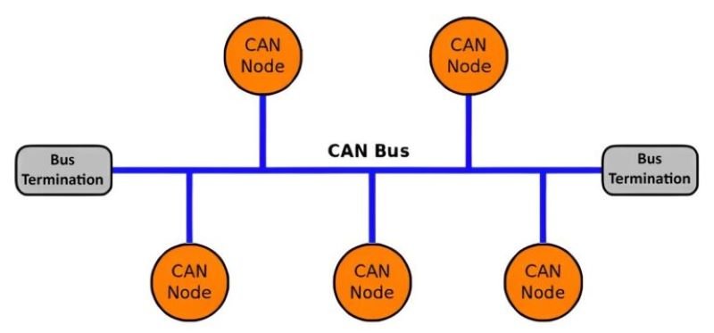
Bus Topology
The CAN Bus network typically uses a linear bus topology, where all nodes are connected to a central bus line. The bus consists of two wires (CAN High and CAN Low), through which messages are transmitted and received by all nodes. This topology minimizes wiring complexity and ensures that any node can communicate with any other node on the bus.
Transceivers
The transceiver is a key component that interfaces between the CAN controller and the physical bus. It converts the data generated by the CAN controller into signals that can be transmitted over the bus. It also receives signals from the bus and converts them back into a format that the controller can understand.
Controllers
The CAN controller is responsible for creating and interpreting CAN messages. It organizes data into frames, adds error-checking information, and manages message prioritization. In modern systems, the CAN controller is often integrated into the ECU itself.
Explanation of Their Roles and Interconnection
In a typical CAN Bus network, the controller in each ECU generates data and passes it to the transceiver, which sends the data across the bus topology to other connected ECUs. The ECUs then process the data to perform specific tasks, like adjusting engine parameters, triggering the brakes, or displaying information on the dashboard.
Together, these components form a network that allows vehicles to function efficiently, making real-time decisions based on data transmitted through the CAN Bus system.
CAN Bus in Automotive Applications
The CAN Bus protocol is integral to the operation of various systems within a vehicle. Its versatility and reliability make it the go-to solution for communication between electronic components in a wide array of automotive applications.
Examples of How CAN Bus is Used in Various Automotive Functions
- Powertrain Control: CAN Bus plays a crucial role in managing the powertrain, which includes the engine, transmission, and associated systems. It enables communication between the engine control unit (ECU), transmission control unit, and various sensors to optimize fuel efficiency, emissions control, and vehicle performance. Real-time data from sensors (such as throttle position and engine speed) is transmitted across the network to regulate engine behavior.
- Body Control: In body control applications, CAN Bus handles the coordination of functions like lighting, window operation, door locks, and climate control. The body control module communicates with various components to ensure these features operate smoothly and efficiently. For example, pressing a button to roll down a window sends a command via CAN Bus to the motor controlling the window.
- Infotainment Systems: Modern vehicles are equipped with infotainment systems that integrate navigation, media playback, and connectivity features like Bluetooth or Wi-Fi. CAN Bus ensures seamless communication between the infotainment unit, speakers, microphones, and user interfaces, allowing for an intuitive and integrated user experience.
- Advanced Driver Assistance Systems (ADAS): ADAS relies heavily on CAN Bus for communication between different sensors and control units, such as cameras, radar, and ultrasonic sensors. These systems, which include lane-keeping assist, adaptive cruise control, and automatic emergency braking, require real-time data transmission to function effectively. CAN Bus facilitates this by ensuring low-latency communication between various safety and driver-assistance modules.
Advantages of CAN Bus in Automotive Systems
The widespread use of CAN Bus in the automotive industry is due to several key advantages it offers, which ensure reliable and efficient communication between various vehicle systems.
Reliability and Robustness in Communication
CAN Bus is designed to operate in harsh automotive environments, making it extremely reliable and robust. It incorporates error detection mechanisms, such as cyclic redundancy checks (CRC) and automatic error correction, ensuring that communication remains accurate even in noisy environments where electromagnetic interference (EMI) may occur.
Real-Time Data Transmission
In automotive applications, many systems require real-time data for safety and control. CAN Bus enables real-time communication by allowing high-priority messages to be transmitted immediately, while lower-priority messages wait their turn. This ensures that time-sensitive information, such as braking or engine data, is processed without delay.
Reduced Wiring Complexity
Before CAN Bus, each system within a vehicle required dedicated wiring, leading to complex and heavy wiring harnesses. CAN Bus reduces the number of wires needed by allowing multiple systems to share a single communication bus. This not only simplifies the vehicle’s wiring architecture but also reduces weight and production costs.
Scalability and Flexibility
CAN Bus is highly scalable, allowing manufacturers to easily add new ECUs or systems without the need for significant changes to the existing network. This flexibility makes it easier to integrate new features or technologies as vehicle designs evolve, keeping pace with innovations in the automotive industry.
Challenges and Limitations
Despite its many benefits, the CAN Bus protocol also faces certain challenges and limitations, especially as vehicles become more complex and data-intensive.
Bandwidth Limitations with Classical CAN
Classical CAN, which operates at a maximum speed of 1 Mbps and supports up to 8 bytes of data per frame, may struggle to handle the increasing data load in modern vehicles. As the number of sensors and systems grows, the bandwidth limitations of Classical CAN can lead to communication bottlenecks, especially in data-heavy applications like infotainment or ADAS.
Latency Issues in Large Networks
In larger CAN Bus networks with many ECUs, latency can become an issue. Although the protocol uses a priority-based arbitration system to manage message collisions, too many nodes can still create delays. In time-critical applications like ADAS, even small latencies can impact performance and safety.
Possible Interference and Security Vulnerabilities
While CAN Bus is robust against electromagnetic interference, it is not immune to security vulnerabilities. Because all nodes on the network share the same bus, an unauthorized device or malicious actor can potentially access and manipulate data. This raises concerns about vehicle security, especially with the rise of connected cars. CAN Bus lacks built-in encryption, making it more vulnerable to hacking.
Future of CAN Bus in the Automotive Industry
The future of CAN Bus in automotive systems is shaped by emerging technologies, evolving vehicle architectures, and the rise of autonomous and connected vehicles.
Emerging Technologies and How CAN Bus is Evolving
One of the key advancements in CAN Bus technology is the introduction of CAN FD (Flexible Data-Rate), which addresses the bandwidth limitations of Classical CAN. CAN FD allows for faster data transmission and larger data payloads, making it more suitable for modern automotive applications. This enables the CAN Bus to remain relevant even as the demand for high-speed communication increases.
Integration with Newer Protocols Like Ethernet, LIN, or MOST
As vehicles become more complex, there is a growing trend toward integrating CAN Bus with newer communication protocols such as Ethernet, LIN (Local Interconnect Network), and MOST (Media Oriented Systems Transport). While CAN Bus remains ideal for control systems and low-latency communication, protocols like Ethernet provide higher data rates, making them suitable for applications like infotainment and autonomous driving. These hybrid communication architectures allow manufacturers to leverage the strengths of each protocol.
Role of CAN Bus in Autonomous Vehicles
In the context of autonomous vehicles, CAN Bus will continue to play a crucial role in core vehicle systems, particularly those involving real-time control and safety. However, the increasing data demands of autonomous systems (such as sensor fusion from LIDAR, cameras, and radar) will likely require additional communication protocols, such as automotive Ethernet, for high-bandwidth data transmission. CAN Bus, with its established reliability, will complement these systems by handling real-time decision-making and control.
Conclusion
In conclusion, The CAN Bus communication protocol has been a cornerstone of automotive systems for decades, enabling efficient, reliable, and cost-effective data exchange between various vehicle components. Its robustness, flexibility, and real-time communication capabilities have made it indispensable for a wide range of applications, from powertrain control to advanced driver assistance systems.
While challenges such as bandwidth limitations and security vulnerabilities exist, advancements like CAN FD and the integration of new protocols are ensuring that CAN Bus remains relevant in modern vehicles. As the automotive industry moves towards more autonomous and connected systems, CAN Bus will continue to be a key player, evolving to meet the demands of future vehicle communication networks.
FAQs
Here are some commonly asked questions about the CAN Bus protocol in the automotive industry:
1. What Makes CAN Bus Different from Other Automotive Protocols?
CAN Bus stands out from other automotive communication protocols like LIN, FlexRay, or Ethernet due to its robustness, simplicity, and cost-effectiveness. While protocols like Ethernet are faster and suitable for high-data applications, CAN Bus offers real-time communication with lower latency, making it ideal for safety-critical systems like engine control and braking.
2. How Does CAN Bus Handle Errors?
CAN Bus has a robust error-handling mechanism built into the protocol. It uses techniques like Cyclic Redundancy Check (CRC), acknowledgment signals, and error counters to detect and correct errors. If an error is detected during data transmission, the CAN Bus system automatically retransmits the message, ensuring data integrity.
3. What Is the Maximum Speed of CAN Bus Communication?
The maximum speed of Classical CAN (CAN 2.0) is 1 Mbps. However, with the introduction of CAN FD (Flexible Data-Rate), the data rate can go up to 8 Mbps, allowing for faster data transmission and larger payloads, which is particularly useful in modern vehicles with high-data requirements.
4. Can CAN Bus Be Used in Systems Other Than Automotive?
Yes, while CAN Bus was originally developed for automotive applications, its reliability and robustness have made it popular in various industries. It is used in industrial automation, medical devices, aerospace, and agriculture machinery, where reliable, real-time data communication is crucial.
5. How Does CAN Bus Prioritize Messages?
CAN Bus uses message arbitration to prioritize messages based on their identifier. Lower numerical IDs have higher priority. During message transmission, if two devices attempt to send messages simultaneously, the one with the lower ID takes precedence, and the other device waits for the bus to be free.