
How to Control RGB LED Wirelessly
In this tutorial, we will guide you through the process of controlling a 1 watt RGB LED using the ESP8266 ESP01 WiFi module. This project allows you to use any Wi-Fi-enabled device to access a web interface for controlling the RGB LED. At the end of this guide, you’ll also find a video demonstration to help you visualize the setup and operation.
Components Needed
- ESP8266 ESP01 WiFi Module
- 1 Watt RGB LED (Common Anode type)
- Resistors (appropriate values for current limiting)
- Breadboard and jumper wires
- 5V power supply (battery or wall adapter)
- A Wi-Fi-enabled device (smartphone, tablet, or computer)
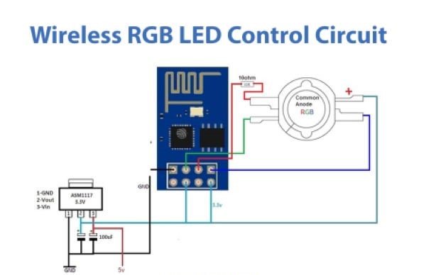
Setting Up the Circuit
- RGB LED Configuration:
- The RGB LED used in this project is a common anode type, meaning the positive terminals of the red, green and blue LEDs are connected together.
- The LED brightness is controlled by varying the voltage applied to the cathodes of the individual LEDs.
- Circuit Connections:
- Connect the common anode (+ve) of the RGB LED to the 5V power supply.
- Connect the cathodes of the red, green and blue LEDs to the GPIO pins of the ESP8266 through current-limiting resistors.
- Ensure the ESP8266 is properly powered by connecting its VCC to the 5V supply and GND to the ground.
Working Explanation
- Powering Up:
- Once the circuit is connected as per the diagram, power it up using the 5V battery or wall adapter.
- Upon booting, the ESP8266 module will initialize, and the RGB LED will show a fade effect through all three colors, indicating that the system is ready.
- Connecting to the Wi-Fi Network:
- On your Wi-Fi-enabled device, open the Wi-Fi settings and look for a new access point named “RGB.”
- Connect to this access point.
- Accessing the Control Webpage:
- Open a web browser on the connected device and enter the IP address
192.168.1.1. - This will bring up a colorful RGB control screen where you can adjust the colors of the RGB LED.
- Open a web browser on the connected device and enter the IP address
Creating the Web Interface
The webpage hosted by the ESP8266 provides a simple interface with different color codes. Each color has a unique code for the red, green, and blue values. The web interface sends these values to the ESP8266, which then adjusts the voltage on the respective pins to control the brightness of each color channel in the RGB LED.
Code Example
Here’s a basic example of the code you might use on the ESP8266 to set up the web server and control the RGB LED:
#include <ESP8266WiFi.h>

const char* ssid = "RGB";
const char* password = ""; // No password

WiFiServer server(80);

// Define the RGB LED pins
const int redPin = D1;
const int greenPin = D2;
const int bluePin = D3;

void setup() {
Serial.begin(115200);

pinMode(redPin, OUTPUT);
pinMode(greenPin, OUTPUT);
pinMode(bluePin, OUTPUT);

WiFi.softAP(ssid, password);

server.begin();
Serial.println("Server started");
}

void loop() {
WiFiClient client = server.available();
if (!client) {
return;
}

String request = client.readStringUntil('\r');
client.flush();

// Parse the request to get RGB values
int redValue = parseValue(request, "red");
int greenValue = parseValue(request, "green");
int blueValue = parseValue(request, "blue");

analogWrite(redPin, redValue);
analogWrite(greenPin, greenValue);
analogWrite(bluePin, blueValue);

client.print("HTTP/1.1 200 OK\r\nContent-Type: text/html\r\n\r\n");
client.print("<html><body><h1>RGB LED Control</h1>");
client.print("<p>Adjust the RGB values to change the LED color</p>");
client.print("<form method='get'>");
client.print("R: <input type='range' name='red' min='0' max='255'><br>");
client.print("G: <input type='range' name='green' min='0' max='255'><br>");
client.print("B: <input type='range' name='blue' min='0' max='255'><br>");
client.print("<input type='submit'></form></body></html>");

client.stop();
}

int parseValue(String request, String name) {
int value = 0;
int index = request.indexOf(name + "=");
if (index != -1) {
int endIndex = request.indexOf('&', index);
if (endIndex == -1) {
endIndex = request.length();
}
value = request.substring(index + name.length() + 1, endIndex).toInt();
}
return value;
}
Conclusion
By following this tutorial, you have successfully set up and controlled a 1 watt RGB LED using the ESP8266 ESP01 WiFi module. This project showcases how to create a simple yet powerful web-based control system for an RGB LED, which can be expanded for various IoT applications. For a step-by-step video demonstration, make sure to watch the video at the bottom of this page.