Zero Crossing Detector Circuit: Working, Waveforms, and Applications
A zero crossing detector (ZCD) is a crucial electronic circuit used to determine when an alternating current (AC) signal transitions through zero volts. These transitions, known as zero crossings, occur when the waveform shifts from positive to negative or vice versa.
Zero crossing detectors are widely used in power electronics, signal processing, and control systems. Their ability to provide precise timing information makes them indispensable in synchronizing circuits and detecting phase changes.
What is a Zero Crossing Detector?
A zero crossing detector is a circuit that outputs a signal whenever the input voltage crosses the zero-voltage level. The circuit identifies the instant when the AC signal’s polarity changes, which is critical for applications such as AC phase control and signal synchronization.
Key Features and Benefits:
- Accuracy: Provides precise detection of zero crossings for accurate timing in electronic systems.
- Noise Immunity: Often designed to suppress noise near the zero crossing, ensuring reliable operation.
- Versatility: Can handle a variety of signal types, including sine waves and square waves.
- Application Range: Suitable for both low-frequency and high-frequency signal processing tasks.
Working Principle of Zero Crossing Detector
How the Circuit Detects Zero Crossings:
A zero crossing detector works by continuously monitoring the input waveform. As the signal transitions through the zero voltage level, the circuit generates an output pulse or toggles its state. This occurs because the detector is designed to respond to changes in polarity (positive to negative or vice versa).
Role of Operational Amplifiers or Comparators:
- Operational Amplifiers (Op-Amps):
Op-amps in open-loop configuration are often used in ZCD circuits. They amplify the small voltage differences around the zero crossing, triggering a distinct output when the signal crosses zero. - Comparators:
Comparators are specialized devices that compare the input voltage with a reference level (zero volts in this case). When the input voltage transitions from above to below the reference, the comparator changes its output state. This output change is then processed further for timing or control purposes.
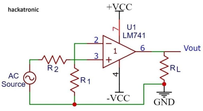
Circuit Diagram
The basic zero crossing detector circuit typically consists of the following:
- An operational amplifier or comparator as the core detection component.
- Input resistor to limit the current.
- A reference voltage set to zero volts (ground).
- Pull-up or pull-down resistors to stabilize the output signal.

Components Used and Their Functions:
- Operational Amplifier/Comparator: Detects the zero crossing and generates the output signal.
- Input Resistor: Protects the op-amp or comparator from excessive current.
- Reference Voltage (Zero Volts): Defines the zero crossing threshold.
- Output Resistor (Optional): Shapes the output signal for further use.
Waveform Analysis
Input and Output Waveform Characteristics:
The input waveform to a zero crossing detector is typically an AC signal, such as a sine wave or square wave. The output waveform is a sharp, binary signal that switches states (high or low) at each zero crossing point. For instance:
- When the input signal crosses from positive to negative, the output might toggle from high to low.
- Similarly, when the input transitions from negative to positive, the output toggles back to high.
This binary signal ensures clear and distinct transitions for timing or synchronization.
Explanation of Phase Relationship and Signal Transition at Zero Crossing:
At the zero crossing point, the input signal’s amplitude momentarily equals zero. The circuit detects this transition and generates an output signal that corresponds to the phase change. This synchronization is vital in applications like motor control and AC phase monitoring, where maintaining the correct timing between signals is crucial.
Applications of Zero Crossing Detectors
Common Applications:
- Power Electronics:
- Used in AC dimmers to control lighting intensity.
- Essential for soft-start circuits in motor drives, ensuring minimal current surges.
- Signal Processing:
- Helps in frequency measurement and signal synchronization.
- Used to detect phase differences in communication systems.
- Synchronization Circuits:
- Synchronizes clock signals in digital systems.
- Maintains timing accuracy in phase-locked loops (PLLs).
Examples of Real-World Usage:
- Triac Control in AC Circuits: For triggering at precise points to reduce electrical noise.
- Digital Frequency Meters: For accurate counting of AC signal frequency.
- Audio Signal Processing: Detecting zero crossings in audio signals for noise gating or effects processing.
Advantages and Limitations
Key Benefits:
- Precision: High accuracy in detecting transitions, even at high frequencies.
- Noise Immunity: Designed to filter out minor fluctuations near zero crossing, reducing false triggers.
- Versatility: Can work with various signal types and frequencies.
- Compact Design: Requires few components, making it suitable for compact circuits.
Potential Drawbacks or Challenges:
- Noise Sensitivity in Poor Designs: Without proper filtering, noise near the zero crossing can cause errors.
- Limited to AC Signals: Not applicable for DC-only applications.
- Response Time: May introduce slight delays in high-speed applications due to circuit response times.
Conclusion
In conclusion, Zero crossing detectors are indispensable components in modern electronics, enabling precise timing and synchronization in diverse applications. Their ability to identify critical transitions in AC signals with accuracy makes them vital in power electronics, signal processing, and control systems. While they come with minor limitations, proper circuit design and noise management can mitigate these challenges. As technology advances, zero crossing detectors will continue to play a pivotal role in innovative solutions, driving efficiency and reliability in electronic systems.


