Voltage Comparator Circuit using OPAMPs
A voltage comparator is a critical component in electronic circuits, primarily used to compare two voltages and determine their relative magnitudes. Operational amplifiers (OPAMPs) are commonly used to build these comparators due to their high input impedance and gain. In this article, we’ll delve into the basics of an OPAMP comparator circuit, explore its types, and discuss its working, characteristics, and applications.
OPAMP Comparator Circuit
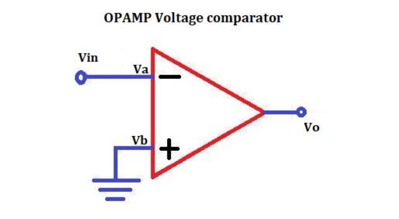
An OPAMP comparator circuit uses an operational amplifier to compare an input voltage against a reference voltage. The output of the OPAMP indicates whether the input voltage is higher or lower than the reference voltage. This simple yet powerful function is foundational in various digital logic circuits, analog-to-digital converters, and other applications requiring precise voltage level detection.
Types of OPAMP Comparators
There are primarily two types of OPAMP comparators:
- Non-Inverting OPAMP Comparator
- Inverting OPAMP Comparator
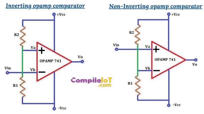
Non-Inverting OPAMP Comparator
In a non-inverting OPAMP comparator, the input voltage is applied to the non-inverting terminal (+) of the OPAMP, while the reference voltage is connected to the inverting terminal (-). When the input voltage exceeds the reference voltage, the output of the comparator swings to the positive saturation level of the OPAMP, usually close to the supply voltage. Conversely, when the input voltage is lower than the reference voltage, the output swings to the negative saturation level.
- The non-inverting terminal receives the input voltage.
- The inverting terminal is connected to a fixed reference voltage.
- The output indicates whether the input is above or below the reference.
Inverting OPAMP Comparator
In an inverting OPAMP comparator, the input voltage is applied to the inverting terminal (-), and the reference voltage is connected to the non-inverting terminal (+). The operation is opposite to that of the non-inverting comparator. If the input voltage is greater than the reference voltage, the output swings to the negative saturation level, and if the input is less, the output goes to the positive saturation level.
- The inverting terminal receives the input voltage.
- The non-inverting terminal is connected to a reference voltage.
- The output reflects the inverse relationship between the input and reference voltages.
Working of Voltage Comparator Circuit
The working principle of a voltage comparator circuit is based on the high gain characteristic of the OPAMP. The OPAMP amplifies the difference between the input and reference voltages to produce an output that is either at the maximum or minimum supply voltage level. This output is a digital signal, making the comparator an essential component in converting analog signals to digital.
- Threshold Voltage: The reference voltage serves as the threshold against which the input voltage is compared.
- Output States: The output can only have two states – high or low, corresponding to the input voltage being higher or lower than the reference.
- Switching Speed: The speed at which the OPAMP transitions from one output state to the other depends on the slew rate of the OPAMP and the speed of the input voltage changes.
Characteristics of a Good Comparator Circuit
A good comparator circuit should have the following characteristics:
- High Gain: To ensure precise comparison, the OPAMP should have a high open-loop gain.
- Low Offset Voltage: A low offset voltage ensures accurate comparison without significant deviation from the reference voltage.
- Fast Response Time: The circuit should be able to respond quickly to changes in input voltage, making it suitable for high-speed applications.
- Low Power Consumption: Especially in battery-powered devices, low power consumption is crucial.
- Hysteresis: Incorporating hysteresis can prevent noise from causing false switching, making the comparator more stable.
Applications of Comparator Circuit
Voltage comparator circuits are used in a wide range of applications:
- Zero-Crossing Detectors: To detect the point where an AC signal crosses zero voltage.
- Level Shifters: To convert one voltage level to another in digital circuits.
- Pulse Width Modulation (PWM): Used in motor control and other applications where precise timing is needed.
- Analog-to-Digital Converters (ADC): Comparators are essential in the design of ADCs, where they convert analog signals into digital form.
- Oscillators: In generating square wave signals, comparators are used in oscillator circuits.
- Overvoltage/Undervoltage Protection: Comparators monitor voltage levels and trigger protective mechanisms when the voltage goes beyond safe limits.