Unlocking the Potential of PIR Motion Sensors with 555 Timer IC Circuits
Brief overview of PIR motion sensors
Passive Infrared (PIR) motion sensors are electronic devices used to detect motion by measuring changes in infrared radiation levels. They are commonly used in security systems, automatic lighting control, and other applications where detecting the presence or movement of people or animals is essential. PIR sensors are cost-effective, reliable, and easy to integrate into various systems, making them a popular choice for motion detection.
Importance of motion detection in various applications
Motion detection is a crucial feature in many modern applications. In security systems, it helps identify unauthorized access and trigger alarms or notifications. In automated lighting systems, motion sensors save energy by turning lights on only when needed. Additionally, motion detection is used in home automation, HVAC systems, and even in some healthcare applications to monitor patient activity. The ability to detect motion enhances safety, security, and efficiency across different domains.
Introduction to the 555 Timer IC and its role in the circuit
The 555 Timer IC is a versatile and widely used integrated circuit that can function as a timer, pulse generator, or oscillator. In the context of a PIR motion sensor circuit, the 555 Timer IC is typically used to process the signal from the PIR sensor and generate an appropriate output. It can be configured to produce a stable output signal whenever motion is detected, making it an essential component in this type of circuit.
Components Required
- PIR Motion Sensor
- 555 Timer IC
- Resistors (various values)
- Capacitors (various values)
- Diodes
- Transistors
- LEDs
- Power supply (e.g., 9V battery)
- Connecting wires
- Breadboard or PCB
Brief description of each component
- PIR Motion Sensor: Detects motion by sensing changes in infrared radiation.
- 555 Timer IC: Processes the signal from the PIR sensor and generates the output.
- Resistors: Control current flow and set timing intervals.
- Capacitors: Store and release electrical energy, used for timing and filtering.
- Diodes: Allow current to flow in one direction, protecting the circuit from reverse voltage.
- Transistors: Amplify the signal from the PIR sensor to drive the output.
- LEDs: Indicate the presence of motion.
- Power supply: Provides the necessary voltage to operate the circuit.
- Connecting wires: Used to connect the components.
- Breadboard or PCB: Used to assemble the circuit.
Understanding PIR Motion Sensors
Working principle of PIR sensors
PIR sensors work by detecting infrared radiation emitted by objects in their field of view. When a warm object, such as a human body, moves within the sensor’s range, it causes a change in the infrared radiation levels. The sensor detects this change and generates an electrical signal. The PIR sensor typically consists of a pair of pyroelectric sensors, which measure the difference in infrared radiation between two points. This differential measurement allows the sensor to detect motion and filter out background infrared radiation.
Typical applications of PIR sensors
PIR sensors are widely used in:
- Security systems: To detect intruders and trigger alarms.
- Automatic lighting: To turn lights on or off based on occupancy.
- Home automation: For controlling devices and appliances based on movement.
- HVAC systems: To adjust heating and cooling based on room occupancy.
- Healthcare: For monitoring patient activity and ensuring safety.
Advantages and limitations of PIR sensors
Advantages:
- Cost-effective
- Low power consumption
- Easy to install and integrate
- Reliable motion detection
Limitations:
- Limited detection range
- Sensitive to environmental changes (e.g., temperature fluctuations)
- Can be triggered by non-human objects (e.g., pets)
Overview of 555 Timer IC
Basic functionality of the 555 Timer IC
The 555 Timer IC is a highly stable device used for generating precise time delays and oscillations. It operates in three main modes: Monostable, Astable, and Bistable. In Monostable mode, it produces a single pulse when triggered. In Astable mode, it generates a continuous square wave. In Bistable mode, it functions as a flip-flop, switching between two stable states.
Different modes of operation (Monostable, Astable, and Bistable)
- Monostable Mode: The 555 Timer produces a single output pulse of a specified duration in response to an input trigger.
- Astable Mode: The 555 Timer continuously oscillates between high and low states, generating a square wave output.
- Bistable Mode: The 555 Timer toggles its output state between high and low with each input trigger, acting like a basic flip-flop.
Why 555 Timer IC is suitable for this circuit
The 555 Timer IC is suitable for PIR motion sensor circuits because of its versatility and ease of use. It can be configured to process the signal from the PIR sensor and generate a stable output when motion is detected. Its ability to operate in Monostable mode is particularly useful, as it allows the circuit to produce a single output pulse of a defined duration, which can be used to drive an alarm, light, or other devices. The 555 Timer’s reliability and wide availability make it an ideal choice for this application.
Circuit Diagram and Explanation
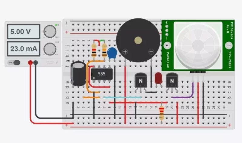
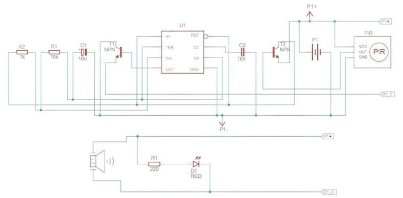
A detailed circuit diagram showing the connections between the PIR sensor, 555 Timer IC, resistors, capacitors and other components.
Step-by-step explanation of the circuit
- Power Supply: Connect the power supply (e.g., 9V battery) to the circuit, ensuring the correct polarity.
- PIR Sensor: Connect the output pin of the PIR sensor to the trigger input (pin 2) of the 555 Timer IC.
- 555 Timer IC: Configure the 555 Timer IC in Monostable mode. Connect pin 1 to ground, pin 8 to the positive supply voltage, and place the necessary resistors and capacitors between pins 6, 7, and ground.
- Output: Connect the output (pin 3) of the 555 Timer IC to an LED or other output device, with a current-limiting resistor in series.
- Reset and Control: Connect pin 4 (reset) to the positive supply voltage and pin 5 (control voltage) to ground through a capacitor.
How the PIR sensor is connected to the 555 Timer IC
The PIR sensor’s output is connected to the trigger input (pin 2) of the 555 Timer IC. When the PIR sensor detects motion, it sends a high signal to pin 2, triggering the 555 Timer IC to generate an output pulse.
Working of the circuit
When the PIR sensor detects motion, it sends a high signal to the trigger input of the 555 Timer IC. This triggers the IC to generate a single output pulse, which turns on the connected LED or other output device for a specified duration. The duration of the output pulse is determined by the values of the resistors and capacitors connected to the 555 Timer IC.
Building the Circuit
Assembly instructions
- Gather all the required components.
- Place the 555 Timer IC on the breadboard.
- Connect the PIR sensor to the breadboard and wire its output to pin 2 of the 555 Timer IC.
- Connect the resistors and capacitors to the appropriate pins of the 555 Timer IC to configure it in Monostable mode.
- Connect the LED or other output device to pin 3 of the 555 Timer IC, with a current-limiting resistor in series.
- Connect the power supply to the circuit, ensuring correct polarity.
Precautions to take while building the circuit
- Double-check all connections to avoid short circuits.
- Ensure the correct polarity of the components, especially the power supply and diodes.
- Use a current-limiting resistor with the LED to prevent it from burning out.
- Handle the components carefully to avoid damaging them.
Testing the circuit
- Power on the circuit.
- Move within the range of the PIR sensor to trigger it.
- Observe if the LED or output device activates for the specified duration.
- Adjust the resistor and capacitor values if necessary to achieve the desired output pulse duration.
Applications of the PIR Motion Sensor Circuit
Various real-world applications
- Home Security: Detecting intruders and triggering alarms.
- Automatic Lighting: Turning lights on or off based on occupancy.
- Energy Management: Controlling HVAC systems based on room occupancy.
- Automated Door Openers: Activating doors in response to motion.
- Healthcare: Monitoring patient movement and activity.
Customization possibilities for different use cases
- Adjustable Timer: Modify the resistor and capacitor values to change the output pulse duration.
- Sensitivity Adjustment: Use different PIR sensors with varying sensitivity levels.
- Additional Outputs: Add more LEDs or other output devices for different indications.
- Wireless Integration: Integrate with wireless modules for remote monitoring and control.
Troubleshooting
Common issues and their solutions
- No Output Signal: Check all connections and ensure the power supply is functioning.
- LED Not Lighting Up: Verify the LED polarity and check the current-limiting resistor.
- False Triggering: Ensure the PIR sensor is properly positioned and not affected by environmental changes.
Tips for ensuring proper functionality
- Use quality components to ensure reliability.
- Double-check all connections before powering the circuit.
- Shield the PIR sensor from direct sunlight and heat sources.
- Regularly test and maintain the circuit to ensure consistent performance.
Conclusion
We explored how to build a PIR motion sensor circuit using the 555 Timer IC, covering the components required, the working principle of PIR sensors, and the functionality of the 555 Timer IC. We also provided a detailed circuit diagram, step-by-step assembly instructions, and troubleshooting tips.
Understanding the operation of PIR sensors and 555 Timer ICs is crucial for designing effective motion detection systems. Both components are versatile and widely used in various applications, making them valuable additions to any electronics enthusiast’s toolkit.
Experimenting with the PIR motion sensor circuit can lead to a deeper understanding of electronics and motion detection technologies. Try customizing the circuit for different applications and explore the possibilities of integrating other sensors and components to create more complex systems.