Understanding CAN Bus: A Comprehensive Guide
Introduction
Developed by Bosch in the 1980s, the Controller Area Network (CAN) bus is a popular communication protocol used in industrial and automotive applications. It was developed to improve data interchange between Electronic Control Units (ECUs), enhancing system efficiency in vehicles. In 1993, CAN was incorporated as an international standard communication system, ISO 11898, in industrial and automobile applications.
Initially designed for multiplex electrical wiring within automobiles to save on copper, the CAN bus is now utilized in various contexts. Though it may seem complex to amateurs, its core principle is straightforward: it is a communication method that allows vehicle systems and devices to communicate with each other, from the car’s stereo to its ABS system. The CAN bus serves as the medium for exchanging instructions among the peer ECUs and other devices.
Basic Principles of CAN Bus
The Controller Area Network (CAN) bus operates on a principle of decentralized networking, where all nodes (or devices) on the network have equal ability to transmit data. This departs from traditional networking models where a central master device controls communication.
CAN Bus Data Transmission
In a CAN network, any node can transmit data when the bus is free. This data is sent in the form of frames, which contain the transmitted information and additional data for error checking and identification.
The CAN bus operates on a “broadcast” principle, meaning that all nodes receive all transmissions. Each node then decides whether to ignore the data or accept it based on the identifier in the CAN frame. This identifier is a label indicating the content of the message, not a source or destination address, allowing multiple nodes to receive and process the same message.
Data transmission in a CAN bus system is based on a differential two-wire interface, enhancing noise immunity in a vehicle’s electrically noisy environment. The two wires, CAN-High (CANH) and CAN-Low (CANL), carry complementary signals. When a node transmits a dominant (0) signal, CAN-High goes to a higher voltage level than CAN-Low. Conversely, when a recessive (1) signal is transmitted, both CAN-High and CAN-Low are at the same voltage level.
CAN Data Frame Structure
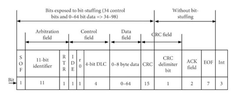
The data in a CAN bus system is transmitted in frames, which consist of several fields. The most critical fields within a data frame are:
- Start of Frame (SOF): 1 bit, initiates frame transmission and signals the beginning of a CAN message.
- Identifier (ID): 11 or 29 bits, a unique message ID that helps prioritize messages.
- Remote Transmission Request (RTR): 1 bit, indicates if the frame is a data request (1) or a data transmission (0).
- Data Length Code (DLC): 4 bits, specifies the number of data bytes included in the frame (0 to 8 bytes).
- Identifier Extension (IDE): 1 bit, differentiates between standard (11-bit ID) and extended (29-bit ID) frames.
- Data Field (Data): 0-64 bits, contains the actual data being transmitted.
- Cyclic Redundancy Check (CRC): 15 bits, used for error-checking purposes.
- Acknowledgment (ACK): 1 bit, indicates successful receipt of the frame.
- End of Frame (EOF): 7 bits, marks the conclusion of the CAN frame transmission.
Error Detection and Handling
One of the key features of the CAN bus system is its efficient error detection and handling capabilities. The system incorporates five methods of error detection:
- Bit Monitoring: Each transmitting node monitors the bus while transmitting.
- Frame Check Sequence (FCS): A cyclic redundancy check (CRC) value calculated based on the frame’s data.
- Acknowledgment Check: Each frame contains an ACK slot for acknowledgment of receipt.
- Frame Format Check: Ensures the frame format is correct.
- Error Frame: Transmitted when an error is detected, causing all nodes to discard the current frame and wait for retransmission.
When an error is detected, the node that detected the error automatically retransmits the frame until it is transmitted without errors. If a node detects too many errors, it goes into an Error Passive state or a bus-off state, ensuring that a faulty node does not disrupt communication.
CAN Bus Architecture
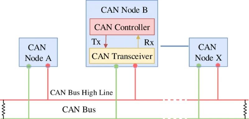
The architecture of a CAN bus system is designed to facilitate efficient communication between multiple nodes. A basic CAN bus system consists of two lines, CAN-High (CANH) and CAN-Low (CANL), connected to all nodes in the system.
Nodes
In a CAN bus system, a node refers to any device connected to the bus capable of sending and receiving messages. Each node has its own Controller and Transceiver, allowing it to interface with the bus. Nodes can range from simple sensors or actuators to complex devices like Engine Control Units (ECUs).
Bus Lines
The bus lines are the physical medium through which data is transmitted between nodes. These lines are typically twisted together to form a twisted pair, reducing electromagnetic interference and improving signal integrity. The differential signaling used in CAN bus systems improves noise immunity by ensuring that any noise picked up by the bus lines affects both lines equally.
The bus lines are terminated at both ends with resistors, typically 120 Ohms, preventing signal reflections that can cause errors in data transmission. The length of the bus lines and the number of nodes connected to them can impact the performance of the CAN bus system. Longer bus lines and more nodes can increase capacitance, slowing down signal rise and fall times and limiting the maximum data rate.
CAN Protocol
The CAN bus is recognized as an international standard for data communication, with several protocols used in CAN bus communication systems, each with its own set of features and capabilities.
CAN Protocols 2.0A and 2.0B
Classical CAN protocols, CAN 2.0A and CAN 2.0B, differ primarily in the length of their identifier fields. CAN 2.0A uses an 11-bit identifier, while CAN 2.0B uses a 29-bit identifier. The longer identifier in CAN 2.0B allows for more unique message identifiers and finer control over message priority but increases the frame length, potentially reducing the maximum data rate.
CAN FD
CAN FD (Flexible Data-rate) was introduced to address some limitations of CAN 2.0A and CAN 2.0B. It supports higher data rates and larger data payloads, making it well-suited for modern applications requiring faster communication and more data throughput. CAN FD allows variable data rates during the transmission of a single frame and increases the maximum data field size from 8 bytes to 64 bytes. Despite these improvements, CAN FD maintains backward compatibility with CAN 2.0A and CAN 2.0B devices.
CAN Bus Variants
There are two widely used CAN bus specifications: ISO 11898-2 (high-speed CAN) and ISO 11898-3 (low-speed CAN). High-speed CAN is intended for real-time, quick data interchange with a maximum data transfer rate of up to 1 Mbps. Low-speed CAN, on the other hand, is fault-tolerant and suitable for systems with less demanding data transfer rates, up to 125 Kbps.
CAN Bus in Automotive Applications
The CAN bus has become integral to modern automotive systems, facilitating communication between various ECUs and sensors. Key applications include engine control, safety systems, body control, and infotainment systems.
Engine Control
The CAN bus plays a crucial role in engine control, enabling the Engine Control Module (ECM) to communicate with sensors and actuators to manage fuel injection, ignition timing, and emissions control.
Safety Systems
The CAN bus is vital for safety systems like Anti-lock Braking Systems (ABS), Electronic Stability Control (ESC), and Advanced Driver Assistance Systems (ADAS), allowing efficient data exchange between sensors, actuators, and control modules.
CAN Bus in Industrial Applications
Beyond automotive systems, the CAN bus is used in various industrial settings, offering robustness, reliability, and flexibility for machine control, sensor networks, and distributed control systems.
Machine Control
The CAN bus enables real-time communication between devices in machine control applications, simplifying wiring and reducing system complexity.
Sensor Networks
The CAN bus is ideal for sensor networks, providing reliable data transmission and supporting advanced features like distributed processing and remote monitoring.
Challenges and Limitations of CAN Bus
Despite its advantages, the CAN bus has limitations, including data rate constraints, network size limitations, and electromagnetic compatibility issues. Alternative communication protocols like Ethernet or FlexRay may be more suitable for high-bandwidth applications.
In summary, the CAN bus is a versatile and robust communication protocol that has become essential in both automotive and industrial applications. Its ability to facilitate efficient and reliable data exchange between multiple devices makes it an invaluable tool in modern electronic systems.
