TRIAC Basics: Symbol, Construction, Working Principle and Practical Applications
A TRIAC, or Triode for Alternating Current, is a semiconductor device widely used in the control of AC power. It is essentially a bidirectional thyristor, capable of conducting current in both directions when triggered. This characteristic makes TRIACs particularly useful for controlling AC power in various electronic applications, including dimmers, motor speed controls, and other AC switching applications.
TRIACs are crucial in modern electronics due to their ability to control AC power efficiently and reliably. They are commonly found in household appliances, industrial equipment, and lighting controls. Their bidirectional conduction property allows them to control power without the need for complex circuits, making them a popular choice for designers and engineers aiming to implement efficient power control solutions.
TRIAC Full Form
Full form of TRIAC: Triode for Alternating Current
The full form of TRIAC is Triode for Alternating Current. This name reflects its ability to control power in AC circuits.
Explanation of the name and its significance
The term “Triode” in TRIAC signifies its three-terminal structure, while “Alternating Current” highlights its capability to operate with AC signals. This naming convention underscores the device’s versatility in handling AC power control, distinguishing it from unidirectional devices like SCRs (Silicon Controlled Rectifiers).
Symbol of TRIAC
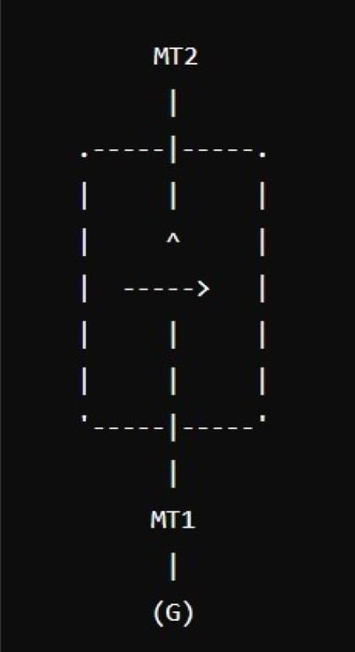
The standard symbol for a TRIAC in circuit diagrams is unique and easily recognizable. It consists of three terminals: the Main Terminal 1 (MT1), the Main Terminal 2 (MT2), and the Gate (G).
Explanation of each part of the symbol
- MT1 and MT2: These are the main terminals through which the main current flows. The current can flow in either direction between these terminals when the TRIAC is triggered.
- Gate (G): The gate terminal is used to trigger the TRIAC. A small current at the gate allows a larger current to flow between MT1 and MT2.
Diagram of the TRIAC symbol
Construction of TRIAC
Detailed description of the internal structure of a TRIAC
A TRIAC is constructed from two SCRs connected in parallel but in opposite directions, sharing a common gate. This internal structure allows the TRIAC to conduct current in both directions when triggered. The device consists of multiple layers of semiconductor material, typically silicon, forming PNPN structures. These layers create junctions that allow the device to switch states when appropriately triggered.
Comparison with other semiconductor devices like SCRs
Unlike an SCR, which can only control current in one direction, a TRIAC can manage current flow in both directions. This bidirectional capability makes TRIACs more versatile for AC applications, whereas SCRs are typically used in DC applications or in circuits where current control in only one direction is required.
Diagram showing the internal construction
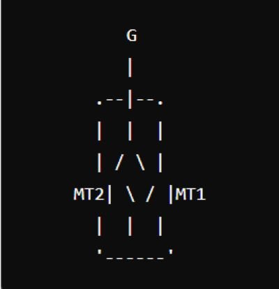
In this diagram:
- The vertical line represents the main current path between MT1 and MT2.
- The horizontal line represents the gate connection used to trigger the device.
- The intersections indicate the internal PNPN layers that form the TRIAC’s structure.
This comprehensive overview introduces the TRIAC, explains its name and symbol, and provides insight into its internal construction and comparison with other semiconductor devices.
Working Principle of TRIAC
Explanation of how a TRIAC operates
A TRIAC operates by controlling the flow of current between its two main terminals, MT1 and MT2, when a small current is applied to its gate terminal. Unlike a unidirectional device like an SCR, a TRIAC can conduct in both directions, making it ideal for AC power control applications.
Detailed working principle with the help of diagrams
When a positive or negative voltage is applied to the gate terminal, the TRIAC becomes conductive, allowing current to flow between MT1 and MT2. This triggering can occur during both the positive and negative cycles of the AC waveform, enabling the TRIAC to control power throughout the entire AC cycle.
Diagram of TRIAC operation:
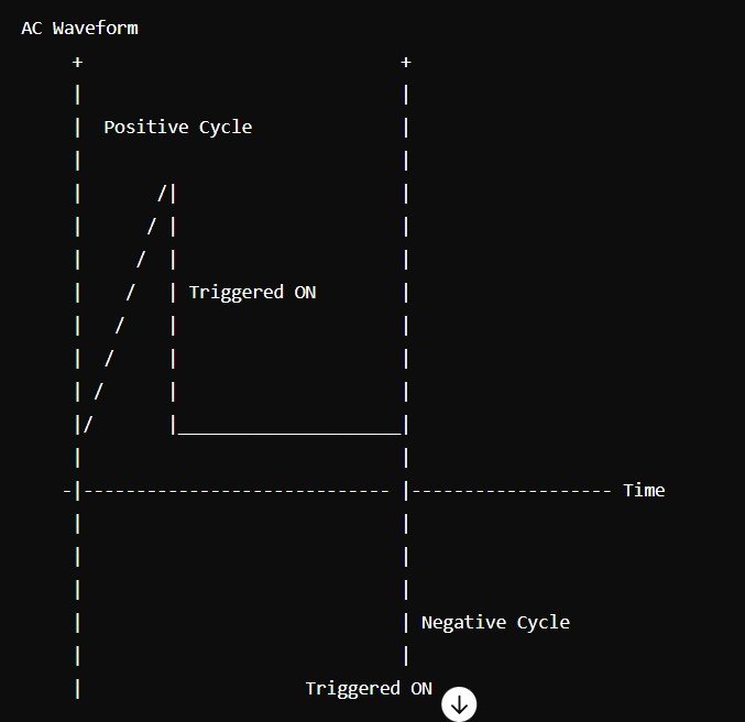
Description of the conduction modes (both positive and negative cycles)
In the positive cycle, when the gate receives a positive pulse, the TRIAC conducts and allows current to flow from MT2 to MT1. Conversely, in the negative cycle, a negative gate pulse enables the current flow from MT1 to MT2. This bidirectional conduction is what makes the TRIAC versatile for AC applications.
VI Characteristics of TRIAC
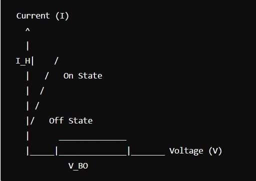
The VI characteristic curve of a TRIAC illustrates its behavior in response to different voltage and current levels. This curve is divided into different regions that represent various states of the TRIAC.
Explanation of the different regions in the VI curve
- Off State: When the voltage across the TRIAC is below a certain threshold and no gate current is applied, the TRIAC remains non-conductive.
- Breakover Voltage (V_BO): The minimum voltage required to turn the TRIAC on without gate current.
- On State: When the TRIAC is triggered by a gate current, it allows a larger current to flow between MT1 and MT2.
- Holding Current (I_H): The minimum current required to keep the TRIAC in the conductive state.
Diagram of the VI characteristic curve
Analysis of how the TRIAC behaves in each region
In the off state, the TRIAC blocks current flow until the breakover voltage is reached or a gate pulse is applied. Upon triggering, the TRIAC enters the on state, allowing current to flow with minimal resistance. If the current falls below the holding current, the TRIAC switches back to the off state.
Applications of TRIAC
Common applications of TRIAC in various fields
TRIACs are commonly used in:
- Light dimmers
- Motor speed controls
- Temperature control systems
- AC power switching
Specific examples and use cases
- Light Dimmers: TRIACs control the power supplied to lamps, adjusting brightness.
- Motor Speed Controls: TRIACs regulate the speed of AC motors in appliances like fans and mixers.
- Temperature Control Systems: TRIACs manage heating elements in thermostats.
- AC Power Switching: TRIACs provide efficient on/off control in various AC circuits.
Advantages of using TRIAC in these applications
- Bidirectional Control: Simplifies circuit design for AC applications.
- Efficient Switching: Reduces power loss and improves performance.
- Compact and Reliable: Suitable for integration into various electronic devices.
Advantages and Disadvantages of TRIAC
List and explanation of the advantages of using TRIAC
- Bidirectional Control: Can control AC power without the need for additional components.
- Efficient Power Handling: Low power loss during switching.
- Compact Size: Suitable for use in small electronic devices.
List and explanation of the disadvantages and limitations
- Sensitivity to Transients: TRIACs can be triggered by noise and voltage spikes.
- Limited Current Handling: May not be suitable for very high-power applications.
- Complex Gate Drive Requirements: Requires careful design to ensure reliable triggering.
Protection of TRIAC
Methods to protect TRIACs in circuits
- Snubber Circuits: Protect against voltage spikes.
- Gate Resistors: Limit the current to the gate to prevent damage.
- Heat Sinks: Dissipate heat to prevent overheating.
Common failure modes and how to avoid them
- Overvoltage: Use snubber circuits and varistors to protect against spikes.
- Overcurrent: Ensure the TRIAC is rated for the expected current and use fuses or circuit breakers.
- Overheating: Implement proper heat dissipation techniques.
Protective components and techniques used in conjunction with TRIACs
- Snubber Circuits: RC networks that protect against voltage transients.
- Varistors: Devices that absorb voltage spikes.
- Heat Sinks: Metal fins or fans to dissipate excess heat.
Conclusion
The TRIAC is a versatile semiconductor device capable of controlling AC power in both directions. It operates by using a gate signal to trigger conduction, with distinct VI characteristics that define its behavior. TRIACs are widely used in applications such as light dimming, motor speed control, and temperature regulation due to their efficient and reliable performance.
TRIAC technology continues to be essential in modern electronics, offering efficient solutions for AC power control. Advances in semiconductor technology may further enhance the performance and reliability of TRIACs, expanding their applications and maintaining their relevance in the evolving electronics landscape.