Stereo Amplifier Circuit 20W + 20W
Introduction
Stereo amplifiers are essential components in audio systems, designed to amplify audio signals and drive speakers to produce sound. Unlike mono amplifiers, which output a single audio channel, stereo amplifiers handle two separate channels—left and right—providing a richer and more immersive listening experience. By delivering distinct audio signals to each speaker, stereo amplifiers create a sense of spatial depth, making them ideal for music, movies, and gaming.
Importance of Having a Good Quality Stereo Amplifier for Audio Systems
A good quality stereo amplifier is crucial for achieving high-fidelity sound reproduction. The amplifier plays a significant role in maintaining the integrity of the audio signal, ensuring that it is amplified without distortion or noise. A well-designed stereo amplifier enhances the clarity, detail, and dynamic range of the sound, making it possible to enjoy music and other audio content as the creators intended. Poor-quality amplifiers, on the other hand, can introduce unwanted artifacts, reduce sound quality, and diminish the overall listening experience.
Power Output of the Circuit: 20W + 20W
The stereo amplifier circuit discussed in this article is designed to deliver a power output of 20W per channel, totaling 40W of output power. This power level is sufficient to drive most home and car audio speakers, providing clear and powerful sound for a wide range of applications. Whether you’re looking to enhance your home audio system or build a custom car audio setup, this 20W + 20W stereo amplifier offers a reliable and efficient solution.
What is a Stereo Amplifier?
A stereo amplifier is an electronic device that amplifies low-level audio signals from a source, such as a CD player, smartphone, or computer, and increases their power to drive speakers. The amplifier takes the weak electrical signals and boosts them, making them strong enough to produce sound through the speakers. The basic working principle involves the use of transistors or operational amplifiers (op-amps) to increase the amplitude of the input signal while maintaining the original waveform.
Explanation of Stereo Channels and Why They Are Used
Stereo amplifiers operate with two separate channels: left and right. Each channel corresponds to a different speaker, creating a two-dimensional sound field. This separation allows the listener to perceive sound coming from different directions, which enhances the sense of depth and realism in the audio. For example, in a music track, the vocals might be centered, while instruments like the guitar and drums are panned to the left and right channels, respectively. This arrangement mimics the natural way we hear sounds in real life and is essential for an immersive listening experience.
Applications of Stereo Amplifiers in Home Audio Systems, Car Audio Systems, etc.
Stereo amplifiers are widely used in various audio applications, including:
- Home Audio Systems: In home theaters, stereo amplifiers are used to drive the front left and right speakers, providing high-quality sound for music and movies.
- Car Audio Systems: Stereo amplifiers are a key component in car audio setups, enhancing the sound quality of the in-car entertainment system.
- Personal Audio Devices: Portable speakers and headphone amplifiers often incorporate stereo amplifiers to deliver better sound quality from compact devices.
- Professional Audio Equipment: In recording studios and live sound setups, stereo amplifiers are used to power studio monitors and PA systems, ensuring accurate sound reproduction.
Circuit Description
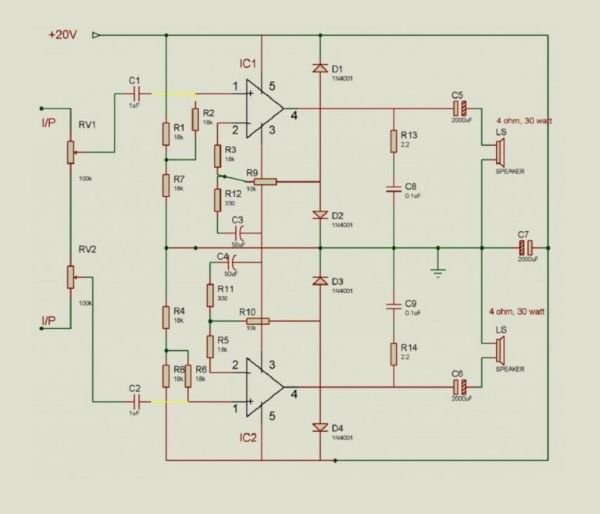
The 20W + 20W stereo amplifier circuit is designed to amplify audio signals and deliver them to two separate speakers. The circuit consists of two identical amplification stages, one for each stereo channel (left and right). Each stage amplifies the input signal and drives a speaker, ensuring balanced and clear sound output. The circuit is powered by a dual power supply, providing the necessary voltage and current to operate the amplifier efficiently.
Explanation of the Key Components Used
- Transistors: The core of the amplification process, transistors are used to boost the audio signal. In this circuit, power transistors handle the high current required to drive the speakers.
- Resistors: Resistors are used to set the gain of the amplifier and stabilize the circuit by controlling the flow of current.
- Capacitors: Capacitors are employed for signal coupling and filtering, ensuring that only the desired audio frequencies are amplified while blocking DC components.
- Operational Amplifiers (Op-Amps): In some designs, op-amps are used for initial signal amplification and processing, providing high gain with minimal distortion.
- Power Supply: The power supply provides the necessary voltage to the amplifier circuit. A dual power supply is often used to allow for both positive and negative voltage swings, which is essential for amplifying AC audio signals.
Block Diagram or Simplified Circuit Diagram
A simplified block diagram of the stereo amplifier circuit can be presented as follows:
- Input Stage: Receives the audio signal and prepares it for amplification.
- Amplification Stage: Boosts the audio signal using transistors or op-amps.
- Output Stage: Delivers the amplified signal to the speakers.
- Power Supply: Provides the necessary power to the circuit, ensuring stable operation.
Component List
Below is a detailed list of components required to build the 20W + 20W stereo amplifier:
| Component | Specification | Quantity | Part Number |
|---|---|---|---|
| Transistors | NPN Power Transistor (e.g., 2N3055) | 2 | 2N3055 |
| Resistors | 10kΩ, 1kΩ, 100Ω (1/4W) | 4 each | – |
| Capacitors | 470µF, 100µF, 10µF (25V) | 2 each | – |
| Operational Amplifiers | Dual Op-Amp IC (e.g., LM358) | 1 | LM358 |
| Power Supply | Dual Power Supply (±12V or ±15V) | 1 | – |
| Heat Sinks | Compatible with 2N3055 | 2 | – |
| PCB | Custom PCB for the amplifier | 1 | – |
| Connectors | Input/Output connectors for audio and power | 1 set | – |
| Potentiometer | 10kΩ (for volume control) | 2 | – |
This list provides all the necessary components, along with their values and part numbers where applicable, to assemble the stereo amplifier circuit.
Working Principle
Detailed Explanation of How the Circuit Works
The 20W + 20W stereo amplifier circuit operates by amplifying low-level audio signals received from an audio source, such as a smartphone or computer, and increasing their amplitude to drive the connected speakers. The circuit consists of two identical channels (left and right), each responsible for amplifying one of the stereo signals. The process begins with the audio signals entering the circuit through input terminals, where they are first conditioned by the input stage.
The input stage typically includes capacitors for DC blocking, ensuring that only AC signals (the audio) are passed to the amplification stages. The signals are then fed into the amplification stage, where transistors or operational amplifiers boost the signal’s amplitude. This stage is crucial as it determines the gain and overall performance of the amplifier. The amplified signals are then passed through the output stage, where they are delivered to the speakers with sufficient power to produce sound.
Discuss the Role of Each Component in Amplifying the Audio Signals
- Transistors: The power transistors (e.g., 2N3055) are the key components responsible for amplifying the audio signals. They operate in the linear region to increase the signal’s amplitude, providing the necessary current and voltage to drive the speakers.
- Resistors: Resistors set the gain of the amplifier by determining the ratio of input to output signals. They also stabilize the circuit and protect other components from excessive current.
- Capacitors: Capacitors are used for coupling (blocking DC components) and bypassing (filtering out noise or stabilizing voltage levels). They ensure that the amplifier only processes the desired audio frequencies.
- Operational Amplifiers (Op-Amps): In circuits that use op-amps, these components provide initial signal amplification with high precision, ensuring low distortion and high gain.
- Power Supply: The dual power supply provides the necessary positive and negative voltages, allowing the amplifier to handle both positive and negative swings of the AC audio signal, which is essential for accurate sound reproduction.
How the Left and Right Channels Are Handled Separately
In a stereo amplifier, the left and right channels are handled separately to maintain the integrity of the stereo sound. Each channel has its own amplification path, consisting of identical components and circuitry. The left audio signal is fed into the left channel’s amplification circuit, while the right audio signal is processed by the right channel. This separation ensures that the audio signals remain distinct, preserving the stereo image and providing a clear and immersive sound experience. The output from each channel is sent to its respective speaker, creating the desired stereo effect.
PCB Design and Layout
Tips for Designing a PCB for the Stereo Amplifier Circuit
When designing a PCB for the 20W + 20W stereo amplifier, several factors must be considered to ensure optimal performance:
- Component Placement: Arrange the components logically to minimize the length of signal paths. Place the input and output connectors at opposite ends of the PCB to reduce interference.
- Ground Plane: Use a solid ground plane to minimize noise and provide a stable reference for the circuit. This helps reduce electromagnetic interference (EMI) and improves signal integrity.
- Power Traces: Use wide traces for the power supply lines to handle the high current required by the amplifier. Ensure that the power traces are as short as possible to reduce voltage drops.
- Heat Management: Position the power transistors and other heat-generating components near the edges of the PCB to allow for better heat dissipation. Use heat sinks if necessary.
Layout Considerations for Minimizing Noise and Crosstalk
- Signal Isolation: Keep the input (low-level) and output (high-level) signal traces separate to avoid crosstalk. Use shielding or guard traces if necessary.
- Decoupling Capacitors: Place decoupling capacitors close to the power pins of the operational amplifiers and other sensitive components to filter out noise from the power supply.
- Trace Routing: Avoid routing signal traces parallel to each other over long distances to prevent crosstalk. If parallel routing is unavoidable, maintain sufficient spacing between the traces.
Assembly and Testing
Step-by-Step Guide for Assembling the Circuit on a PCB or Breadboard
- Prepare the Components: Gather all the components listed in the component list. Ensure that you have the correct values and types of components.
- Mount the Components: Start by placing the components on the PCB or breadboard according to the circuit diagram. Begin with the smaller components like resistors and capacitors, followed by larger components such as transistors and connectors.
- Solder the Components: If using a PCB, solder each component in place, making sure the connections are secure and free of cold solder joints. Double-check the orientation of polarized components like capacitors and diodes.
- Connect the Power Supply: Attach the power supply to the circuit, ensuring the correct polarity. Verify the voltage levels before powering the circuit.
- Connect the Input and Output: Attach the audio input source to the input terminals and connect the speakers to the output terminals.
Testing the Circuit for Correct Operation
- Initial Power-On: Power on the circuit without any input signal and measure the output voltage. It should be close to zero if the circuit is functioning correctly.
- Apply an Input Signal: Feed a known audio signal into the input and monitor the output on an oscilloscope. The output waveform should be a larger, amplified version of the input signal.
- Check for Distortion: Listen to the output through the speakers and check for any audible distortion or noise. If the sound is clear, the circuit is functioning as expected.
Troubleshooting Common Issues
- No Output: Check all connections, especially the power supply and input connections. Ensure that the transistors are correctly oriented and functioning.
- Distorted Sound: Verify the integrity of the capacitors and resistors. Check for any solder bridges or short circuits on the PCB.
- Overheating: If the transistors or other components are overheating, ensure that heat sinks are properly installed, and the power supply voltage is within the recommended range.
Performance Analysis
The 20W + 20W stereo amplifier is designed to deliver high-quality sound with minimal distortion and noise. The expected performance parameters include:
- Frequency Response: The amplifier should exhibit a flat frequency response across the audio spectrum (20Hz to 20kHz), ensuring accurate reproduction of bass, midrange, and treble frequencies.
- Distortion: The total harmonic distortion (THD) should be low, ideally below 0.1%, to ensure clear and undistorted sound output.
- Signal-to-Noise Ratio (SNR): A high SNR, typically above 80dB, indicates that the amplifier produces minimal noise relative to the audio signal, resulting in a cleaner sound.
If available, include test results or measurements taken during the performance analysis. For example:
- Frequency Response Graph: A plot showing the amplifier’s response across different frequencies.
- THD Measurement: A reading or graph showing the total harmonic distortion at various output levels.
- SNR Measurement: The signal-to-noise ratio calculated based on the noise floor and the maximum output level.
Applications
Possible Use Cases for the Stereo Amplifier Circuit
The 20W + 20W stereo amplifier can be used in a variety of applications, including:
- Home Audio Systems: Ideal for driving bookshelf or floor-standing speakers in a home stereo setup.
- Car Audio Systems: Can be integrated into a custom car audio system to power front or rear speakers.
- Portable Speaker Systems: Suitable for use in DIY portable speaker projects, providing ample power for compact speakers.
- Desktop Audio: Can be used to drive high-quality desktop speakers for a computer or gaming setup.
Integration into Different Audio Systems
The amplifier can be easily integrated into existing audio systems by connecting it between the audio source (e.g., media player, computer) and the speakers. It can be housed in a custom enclosure and fitted with volume controls and input/output connectors for ease of use.
Conclusion
In this article, we have explored the design and construction of a 20W + 20W stereo amplifier circuit. We covered the working principle, key components, and step-by-step assembly instructions. We also discussed important considerations for PCB design, testing, and troubleshooting.
The 20W + 20W stereo amplifier circuit offers a practical and effective solution for a wide range of audio applications. Its ability to deliver clear and powerful sound makes it an excellent choice for both hobbyists and audio enthusiasts. With careful construction and proper component selection, this amplifier can provide reliable performance and enhance the audio experience in any setting.