LM3915 Based LED VU Meter Circuit Diagram And Working
Introduction
The LED VU (Volume Unit) Meter is a visual representation of the audio signal strength in various audio systems. It provides a dynamic display of audio levels using a series of LEDs, where each LED represents a specific audio level. This makes it easier to monitor audio levels in real-time, ensuring that the sound output is within desired limits and preventing distortion or damage to audio equipment.
The LM3915 IC is the heart of the LED VU Meter circuit. It is a monolithic, integrated circuit that simplifies the process of driving 10 LEDs in response to an analog input signal. What makes the LM3915 particularly useful is its logarithmic scale, where each step in the LED sequence corresponds to a decibel increase in the input signal. This makes it ideal for audio applications, where the human ear perceives sound levels on a logarithmic scale.
This circuit is widely used in audio amplifiers, mixers, recording equipment, and even DIY audio projects. The ability to visually monitor audio levels makes the LM3915-based VU meter indispensable in both professional and hobbyist environments.
Components Required
To build the LM3915-based LED VU Meter, you’ll need the following components:
- LM3915 IC: The core of the circuit, responsible for driving the LEDs based on the input signal.
- LEDs (10): These LEDs represent the audio levels, with each LED corresponding to a different signal strength.
- Resistors: Used to set the reference voltage and current for the LEDs.
- Capacitors: Used for power supply decoupling and to smooth out the input signal.
- Power Supply: Typically a 5V or 12V DC supply, depending on the circuit design.
- Audio Signal Source: An input source like a microphone, audio player, or any device that outputs an audio signal.
Brief Description of Each Component’s Role:
- LM3915 IC: This IC senses the audio signal and illuminates the LEDs in proportion to the signal’s strength, using its internal voltage reference and comparators.
- LEDs: These display the signal level visually. The more LEDs lit, the stronger the signal.
- Resistors: Set the LED current and reference voltage. They determine the brightness of the LEDs and the sensitivity of the meter.
- Capacitors: Stabilize the power supply and filter the input signal, preventing unwanted fluctuations and noise.
- Power Supply: Provides the necessary voltage for the circuit to function.
- Audio Signal Source: Provides the input signal that the circuit will measure and display.
Understanding the LM3915 IC
The LM3915 is a logarithmic display driver IC that can drive 10 LEDs, LCDs, or vacuum fluorescent displays, making it ideal for audio level indicators. The IC takes an analog input signal and lights up a bar or dot display in a logarithmic fashion, where each LED represents a step in decibel (dB) levels.
Pin Configuration and Functions:
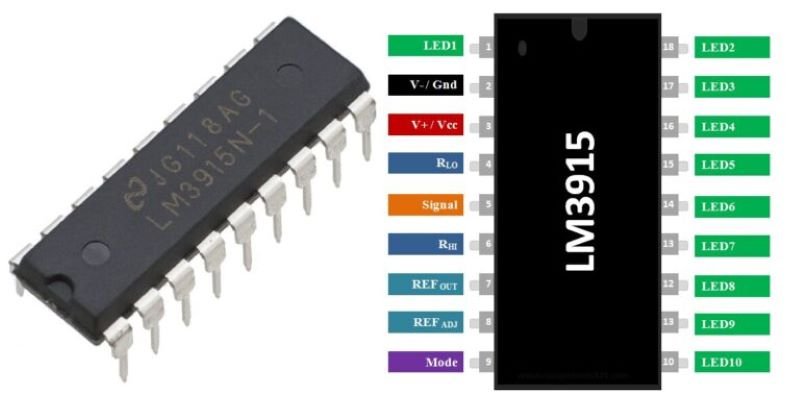
- Pin 1 (LED 1) to Pin 10 (LED 10): These pins are connected to the LEDs. Each pin corresponds to a different LED in the display.
- Pin 11 (Ref Out): Provides a reference voltage output that can be used to set the LED current.
- Pin 12 (Ref Adj): Allows adjustment of the reference voltage, which in turn adjusts the LED current.
- Pin 13 (V+): The positive supply voltage pin.
- Pin 14 (RLO): The lower reference voltage for the input signal.
- Pin 15 (Input): Receives the analog input signal.
- Pin 16 (GND): Ground pin for the circuit.
Internal Structure and Working Principles: The LM3915 contains a series of comparators that compare the input signal with a set of reference voltages. As the input voltage increases, it crosses these reference thresholds, causing the corresponding LEDs to light up. The logarithmic nature of the IC means that each successive LED represents a higher voltage level by a factor of approximately 1.25 times the previous one, which aligns well with the way human hearing perceives sound levels.
Comparison with Similar ICs (LM3914, LM3916):
- LM3914: Displays in a linear fashion, where each LED represents an equal step in voltage, making it more suitable for non-audio applications.
- LM3916: Designed specifically for VU meter applications, with a dB scale tailored for broadcast and recording equipment. It has a slightly different step distribution compared to the LM3915.
The LM3915 stands out for its general-purpose logarithmic scale, making it a versatile choice for audio level indicators in various contexts.
Circuit Diagram
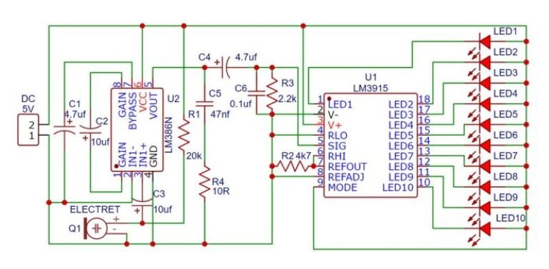
Presentation of the Circuit Diagram: The circuit diagram for the LM3915-based LED VU Meter is relatively simple and typically consists of the LM3915 IC, 10 LEDs, a few resistors, capacitors, and the audio input source. The LM3915 IC is connected to the LEDs in such a way that each LED lights up according to the amplitude of the input audio signal.
Explanation of How the Circuit is Assembled:
- Power Supply: The V+ pin (Pin 13) of the LM3915 is connected to the positive terminal of the power supply, and the GND pin (Pin 16) is connected to the negative terminal.
- LED Connections: Pins 1 to 10 of the LM3915 are connected to the cathode of each LED. The anodes of the LEDs are connected to the positive supply through current-limiting resistors.
- Input Signal: The audio signal is fed into the circuit through a coupling capacitor connected to the input pin (Pin 5) of the LM3915.
- Reference Voltage and Adjustment: A resistor is connected between Pin 7 (Ref Out) and Pin 8 (Ref Adj) to set the reference voltage, which determines the current flowing through the LEDs and their brightness.
Important Connections and How the Components are Wired Together:
- Reference and LED Brightness Control: The reference voltage at Pin 7 controls the brightness of the LEDs. By adjusting the resistor between Pin 7 and Pin 8, you can fine-tune the brightness.
- Signal Grounding: Ensure that the audio signal’s ground is properly connected to the circuit ground to prevent noise and ensure accurate readings.
- Power Supply Decoupling: A capacitor should be placed across the power supply pins to filter out any noise or fluctuations, ensuring stable operation.
Design Considerations or Alternatives:
- LED Arrangement: You can arrange the LEDs in either a bar graph or dot mode. In bar graph mode, all LEDs up to the current level light up, while in dot mode, only the LED corresponding to the current level lights up. This can be selected by connecting the Mode pin (Pin 9) to either ground or V+.
- Sensitivity Adjustment: If the input signal is too weak or too strong, you can adjust the input resistor or use a potentiometer to vary the input signal level.
Working Principle
Step-by-Step Explanation of How the VU Meter Functions:
- Audio Signal Input: The input audio signal, after being coupled through a capacitor, is fed into the LM3915 IC at Pin 5.
- Signal Comparison: The LM3915 has an internal series of comparators that compare the input signal voltage to predefined reference levels.
- LED Activation: As the input signal voltage increases, it crosses these reference thresholds, causing the corresponding LEDs to light up sequentially.
- Logarithmic Scale: The LM3915 uses a logarithmic scale where each LED represents a decibel (dB) level, making it ideal for audio applications where the human ear perceives sound logarithmically.
- LED Display: The LEDs light up in response to the signal’s amplitude, providing a visual representation of the audio levels.
How the LM3915 Drives the LEDs in Response to the Input Audio Signal: The LM3915 drives the LEDs directly without requiring additional current-limiting resistors for each LED. The internal circuitry of the LM3915 ensures that each LED lights up at the appropriate signal level, based on the logarithmic scale, providing a smooth transition from one LED to the next.
Discussion on the Logarithmic Scale Used by the LM3915: The logarithmic scale is particularly useful for audio applications because it allows the meter to cover a wide range of signal levels while still providing good resolution at lower levels. Each step on the scale corresponds to a dB increase in the input signal, which matches the way human hearing perceives changes in loudness.
Explanation of How Different Audio Levels Correspond to Different LED Levels: As the audio signal’s amplitude increases, more LEDs light up. For example:
- A low signal might only light up the first few LEDs, indicating a low audio level.
- A moderate signal will light up half the LEDs, indicating a medium level.
- A strong signal will light up all the LEDs, indicating a high audio level.
Adjustments and Calibration
Explanation of How to Calibrate the VU Meter for Different Audio Levels:
- Adjusting the Reference Voltage: By changing the value of the resistor between Pins 7 and 8, you can adjust the reference voltage, which in turn changes the sensitivity of the meter.
- Input Signal Level: If the audio input signal is too high or low, you can adjust the input resistor or use a potentiometer to bring it within the desired range.
- Mode Selection: Choose between bar and dot mode to display the audio levels as a continuous bar or a single dot, depending on your preference.
Tips on Adjusting the Sensitivity and Reference Voltage:
- Fine-Tuning: Use a potentiometer to fine-tune the reference voltage for precise control over LED brightness and sensitivity.
- Test with Different Audio Sources: Test the VU meter with different audio sources to ensure that it responds appropriately to various signal strengths.
How to Modify the Circuit for Different Audio Sources or Environments:
- Amplification: If the input signal is too weak, consider adding a preamplifier stage before the input to boost the signal level.
- Filtering: Add a low-pass filter to remove any high-frequency noise that might interfere with the meter’s accuracy.
Applications
Common Applications of the LED VU Meter Circuit:
- Audio Equipment: Used in amplifiers, mixers, and equalizers to monitor audio levels.
- Recording Studios: Essential in recording setups to ensure proper signal levels and avoid distortion.
- DIY Projects: Popular among hobbyists for building custom audio visualizers and sound-level meters.
Examples in Audio Equipment, Recording Studios, and DIY Projects:
- Home Audio Systems: Integrated into amplifiers and receivers to visually monitor output levels.
- Broadcast Equipment: Used in radio and television broadcasting to maintain consistent audio levels.
- Custom Audio Projects: Hobbyists use the VU meter in speaker systems, visualizers, and other audio-related DIY projects.
Troubleshooting
Common Issues That May Arise While Building or Using the Circuit:
- LEDs Not Lighting Up: Could be due to incorrect wiring, a faulty LM3915 IC, or insufficient input signal.
- Inconsistent LED Brightness: May result from incorrect reference voltage or a power supply issue.
- Noise and Flickering: Often caused by poor grounding or inadequate power supply filtering.
Solutions and Tips for Debugging the Circuit:
- Check Connections: Ensure all components are properly connected and that there are no shorts or open circuits.
- Test the Power Supply: Verify that the power supply is stable and providing the correct voltage.
- Use Proper Grounding: Ensure that the ground connections are secure and that the input signal is properly grounded.
Precautions to Ensure Proper Functioning:
- Double-Check Component Values: Ensure all resistors, capacitors, and other components are the correct values.
- Avoid Overloading: Do not exceed the voltage or current ratings of the components, especially the LEDs and the LM3915 IC.
Conclusion
Summary of the Key Points Discussed in the Article:
- The LM3915-based LED VU Meter is a practical and versatile circuit that visually displays audio levels using a logarithmic scale.
- The LM3915 IC simplifies the design by driving 10 LEDs with minimal external components, making it ideal for audio applications.
Final Thoughts on the Usefulness and Versatility of the LM3915-Based LED VU Meter: The LM3915-based VU meter is an essential tool in both professional and hobbyist audio setups. Its ability to visually represent audio levels in real-time makes it invaluable in ensuring optimal audio performance and preventing distortion.