ESP8266 NodeMCU: Pinout, Flashing, and Initial Setup Guide
The ESP8266 is a low-cost Wi-Fi microcontroller designed for IoT (Internet of Things) projects. Known for its versatility, it has become popular among hobbyists and professionals. In this article, we will cover the ESP8266 pinout, flashing the firmware, and the initial setup in simple terms.
What is ESP8266?
The ESP8266 is a small, powerful microcontroller with built-in Wi-Fi capabilities. It can be programmed using several environments like Arduino IDE, NodeMCU, or MicroPython. It’s commonly used in IoT projects, including smart home systems, wireless sensors, and other automation tasks.
ESP8266 Pinout
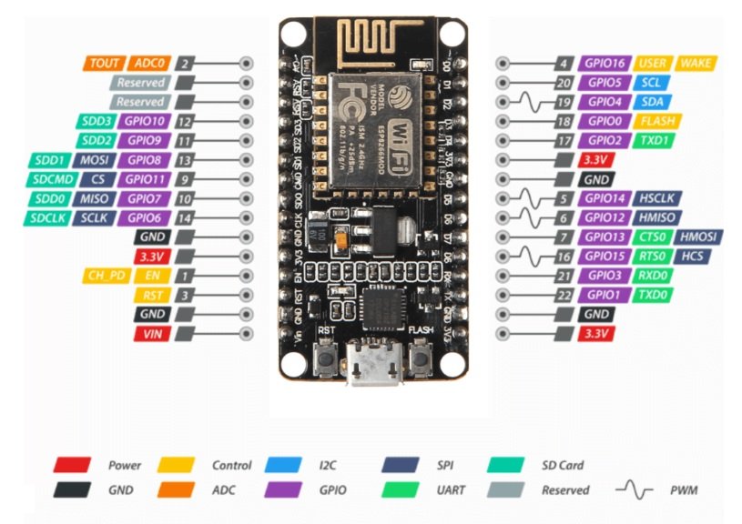
The ESP8266 comes in different modules, but the ESP-12E and ESP-12F (commonly integrated into development boards like NodeMCU) are the most widely used. Here’s an overview of its pinout:
- Power Pins:
- VCC (3.3V): Connect to a 3.3V power supply.
- GND: Ground pin, necessary for completing the circuit.
- GPIO Pins:
- General Purpose Input/Output (GPIO) pins allow you to interface with sensors, actuators, and other components.
- Common GPIO pins: GPIO0 to GPIO16.
- Communication Pins:
- TX (Transmit): Sends serial data.
- RX (Receive): Receives serial data.
- These pins are used for serial communication and flashing the firmware.
- Special Pins:
- EN (Enable): Enables the chip when connected to HIGH.
- RST (Reset): Resets the chip when pulled LOW.
- ADC (Analog-to-Digital Converter): Reads analog input (0 to 1V).
Setting Up ESP8266: Initial Steps
Before using the ESP8266, you need to prepare it for your project. Let’s break it down step by step:
1. Hardware Requirements
- ESP8266 development board (e.g., NodeMCU or Wemos D1 Mini)
- Micro USB cable
- Computer with Arduino IDE installed
- Breadboard and jumper wires (optional)
2. Installing Arduino IDE
- Download the Arduino IDE from its official website: Arduino IDE.
- Install the IDE and open it.
3. Adding ESP8266 to Arduino IDE
- Go to File > Preferences.
- In the Additional Board Manager URLs field, paste the following link:
https://arduino.esp8266.com/stable/package_esp8266com_index.json - Click OK.
- Next, go to Tools > Board > Boards Manager.
- Search for “ESP8266” and install the package.
4. Connecting ESP8266 to Your Computer
- Use a USB cable to connect the ESP8266 development board to your computer.
- Select the correct board and port in Arduino IDE:
- Go to Tools > Board and choose your board (e.g., NodeMCU 1.0).
- Go to Tools > Port and select the correct COM port.
Flashing the Firmware
Flashing firmware updates or custom programs onto the ESP8266 is essential. Here’s how you can do it:
1. Download the Firmware
- If you want to use NodeMCU or MicroPython, download the respective firmware files from their official sources.
2. Use a Flashing Tool
- Download a flashing tool like esptool.py or a GUI-based tool like NodeMCU Flasher.
- Follow these steps for esptool.py:
- Install Python on your computer if not already installed.
- Install esptool using the command:
pip install esptool - Put the ESP8266 in flash mode:
- Connect GPIO0 to GND and reset the board.
- Use the command to erase the existing firmware:
esptool.py --port COMx erase_flashReplace
COMxwith the correct port. - Flash the new firmware:
esptool.py --port COMx write_flash -fm dio -fs 1MB 0x00000 firmware.bin
Uploading Your First Code
Let’s upload a simple program using the Arduino IDE to blink an LED.
1. Connect an LED
- Connect the positive leg of the LED to GPIO2.
- Connect the negative leg to a 330-ohm resistor, which goes to GND.
2. Write the Code
Open the Arduino IDE and write the following code:
void setup() {
  pinMode(2, OUTPUT); // Set GPIO2 as an output
}

void loop() {
  digitalWrite(2, HIGH); // Turn the LED on
  delay(1000);           // Wait for 1 second
  digitalWrite(2, LOW);  // Turn the LED off
  delay(1000);           // Wait for 1 second
}
3. Upload the Code
- Click the Upload button in Arduino IDE.
- The code will be compiled and flashed onto the ESP8266.
- The LED should start blinking!
Common Issues and Troubleshooting
- Upload Errors:
- Ensure the correct board and port are selected.
- Check the USB cable and connection.
- Power Problems:
- The ESP8266 requires a stable 3.3V power supply. Avoid powering it directly from the 5V pin of the Arduino.
- Wi-Fi Connectivity:
- If the ESP8266 cannot connect to Wi-Fi, check the SSID and password in your code.
Conclusion
The ESP8266 is a powerful and affordable microcontroller for IoT applications. By understanding its pinout, learning how to flash firmware, and completing the initial setup, you can unlock its full potential. Whether you’re a beginner or an experienced developer, the ESP8266 is a great choice for your next project. Happy coding!


