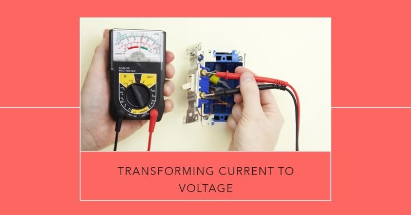
Current to Voltage Converter(I to V)
Current to Voltage (I to V) conversion is a fundamental process in electronic circuits where the input current is converted into a proportional output voltage. This conversion is essential in various applications, particularly when dealing with sensors that output current instead of voltage. By converting this current to a measurable voltage, it becomes easier to process and analyze the signal in analog or digital circuits.
Introduction
I to V converters are vital in applications involving sensors like photodiodes, thermocouples, and current output devices where the output signal is in the form of current. These converters are also used in data acquisition systems, where the current output from different sensors needs to be converted into a voltage that can be fed into an Analog-to-Digital Converter (ADC) for digital processing. Additionally, I to V converters are crucial in analog signal processing, instrumentation and communication systems, ensuring accurate and stable signal conversion.
Types of I to V Converters
I to V converters can be designed using various components and techniques, depending on the application’s requirements. The most common types include:
- Operational Amplifier (Op-Amp) Based I to V Converters: These use an operational amplifier in a feedback configuration to produce a voltage proportional to the input current.
- Resistor-Based I to V Converters: In this simple method, a resistor is used to convert current directly into voltage according to Ohm’s law.
- Transistor-Based Converters: These utilize transistors in configurations like current mirrors to achieve current to voltage conversion.
- Current Mirrors and Other Techniques: Advanced methods like current mirrors offer high precision and are used in integrated circuits.
Basic Concept of Current to Voltage Conversion
Explanation of the Fundamental Principle
The basic principle behind current to voltage conversion is to utilize a circuit element that responds to the input current by generating a proportional voltage across it. This is typically achieved by passing the current through a resistor or by using an operational amplifier in a feedback configuration. The resulting voltage can then be easily measured, processed, or fed into other parts of an electronic system.
Mathematical Relationship between Current and Voltage
The mathematical relationship in an I to V converter can be derived from Ohm’s law, which states: V=I×RV = I \times R Where:
- VV is the output voltage.
- II is the input current.
- RR is the resistance through which the current passes.
In Op-Amp based converters, the relationship might involve additional factors, such as the gain of the amplifier, but the fundamental concept remains the same: the output voltage is directly proportional to the input current.
Examples of Where I to V Conversion is Needed
- Photodiodes: When light strikes a photodiode, it generates a current proportional to the light intensity. This current needs to be converted to a voltage for further processing.
- Thermocouples: These devices generate a small current in response to temperature changes, requiring an I to V converter to produce a usable voltage signal.
- Current Sensing: In power supply circuits, current sensing is often done by converting the sensed current to a voltage for monitoring and control purposes.
Operational Amplifier (Op-Amp) Based I to V Converter
In an Op-Amp based I to V converter, the input current is fed into the inverting input of the operational amplifier. A feedback resistor is connected between the output and the inverting input, creating a virtual short circuit at the inverting input due to the high gain of the Op-Amp. The Op-Amp adjusts its output to maintain a zero voltage difference between its inputs, resulting in an output voltage that is proportional to the input current, determined by the value of the feedback resistor.
Advantages:
- High precision and stability.
- Low output impedance, making it suitable for driving subsequent stages.
- Flexibility in adjusting the output voltage by changing the feedback resistor.
Limitations:
- Requires a power supply for the Op-Amp.
- Potential issues with offset voltage and bias current, which can affect accuracy in low-current applications.
Resistor-Based I to V Converter
In a resistor-based I to V converter, the input current flows through a resistor, generating a voltage across the resistor according to Ohm’s law. The output voltage is directly proportional to the input current, with the proportionality constant being the resistance value. This method is straightforward and does not require active components, making it suitable for low-cost and low-power applications.
Pros:
- Simple and cost-effective.
- No need for an external power supply.
- Suitable for high-current applications where the voltage drop across the resistor is acceptable.
Cons:
- Limited precision, especially at low current levels.
- High output impedance, which can affect subsequent stages.
- Sensitivity to temperature variations, which can change the resistance value.
Other Methods
Mention of Other Less Common Techniques
- Transistor-Based Converters: These use transistors in configurations like current mirrors to achieve current to voltage conversion. They offer high precision and are often used in integrated circuits where space and power efficiency are critical.
- Current Mirrors: A current mirror circuit replicates the input current in a different branch, allowing for the conversion to a voltage across a resistor in that branch. This method is commonly used in analog integrated circuits.
- Hybrid Methods: Some advanced I to V converters combine different techniques, such as using an Op-Amp with a transistor-based current mirror to achieve both high precision and low power consumption.
Applications of I to V Converters
Use in Sensor Interfaces (e.g., Photodiodes)
I to V converters are widely used in sensor interfaces where the output of the sensor is in the form of current. Photodiodes are a prime example: they generate a current proportional to the intensity of light falling on them. This current is typically very small and needs to be converted into a voltage signal that can be easily processed by other electronic circuits. An I to V converter provides a simple and effective way to achieve this, allowing accurate measurement and further processing of the light intensity signal.
Data Acquisition Systems
In data acquisition systems, multiple sensors may be used to monitor various parameters such as temperature, pressure, or light. Many of these sensors produce current outputs, which need to be converted to voltage for digital conversion and analysis. I to V converters play a crucial role in these systems, ensuring that the current signals from the sensors are accurately translated into voltage signals that can be fed into an Analog-to-Digital Converter (ADC) for further processing and storage.
Analog-to-Digital Conversion
Analog-to-digital conversion is a critical process in modern electronics, especially in digital signal processing. For sensors and transducers that output current, an I to V converter is necessary to produce a voltage signal compatible with ADCs. The accuracy and stability of the I to V converter directly impact the quality of the digitized signal, making these converters essential in achieving high-fidelity digital representations of analog signals.
Measurement Systems and Instrumentation
In measurement systems and instrumentation, I to V converters are used to convert the output current of various transducers into a measurable voltage. This is particularly important in precision instruments where accurate and stable measurement of physical quantities like temperature, pressure, or flow is required. The converter’s role is to ensure that the current signal is accurately transformed into a voltage that can be displayed, recorded, or further processed.
Practical Considerations
Accuracy and Precision
Factors Affecting the Accuracy of Conversion The accuracy of a current to voltage converter depends on several factors:
- Component Tolerances: The precision of the resistors and other components used in the circuit can significantly impact the accuracy of the conversion. High-precision components are necessary to minimize errors.
- Op-Amp Characteristics: In Op-Amp based converters, the offset voltage, bias current, and bandwidth of the Op-Amp can affect accuracy. Low-offset and low-bias current Op-Amps are preferred for high-precision applications.
- Circuit Layout: Proper PCB layout techniques, such as minimizing parasitic capacitance and inductance, are essential to maintaining accuracy, especially at high frequencies.
Temperature Stability
Impact of Temperature on Circuit Performance Temperature variations can affect the performance of I to V converters by changing the resistance values, Op-Amp characteristics, and other component behaviors. For example:
- Resistor Temperature Coefficient: The resistance of resistors can change with temperature, leading to variations in the output voltage. Using resistors with a low temperature coefficient helps mitigate this effect.
- Op-Amp Temperature Drift: The offset voltage and bias current of Op-Amps can drift with temperature, impacting the accuracy of the converter. Choosing temperature-stable Op-Amps and incorporating temperature compensation techniques can enhance performance.
Power Supply Considerations
Influence of Power Supply Variations on Output The stability and quality of the power supply are crucial for the reliable operation of I to V converters, especially those using Op-Amps. Variations in the power supply voltage can cause changes in the Op-Amp’s output, leading to inaccuracies in the conversion. Using low-noise, stable power supplies and adding decoupling capacitors can reduce the impact of power supply fluctuations. Additionally, ensuring that the power supply voltage is within the specified range of the components used can prevent performance degradation.
Simulation and Example Circuits
Provide Example Circuit Simulations Using Software like SPICE
To demonstrate the performance of I to V converters, circuit simulations can be conducted using software like SPICE. For example:
- Op-Amp Based I to V Converter Simulation: Set up a simulation with a current source feeding into an Op-Amp based converter with a feedback resistor. Analyze the output voltage for various input current levels to verify the linearity and accuracy of the conversion.
- Resistor-Based I to V Converter Simulation: Simulate a simple resistor-based converter and observe the output voltage as the input current changes. Compare the results with theoretical calculations to validate the design.
Real-World Examples with Component Values
- Example 1: An Op-Amp based I to V converter with a 10 kΩ feedback resistor and an LM741 Op-Amp. The input current ranges from 0 to 1 mA, resulting in an output voltage range of 0 to 10 V.
- Example 2: A resistor-based I to V converter using a 1 kΩ resistor. For an input current of 0 to 10 mA, the output voltage ranges from 0 to 10 V.
Analysis of Results and Discussion
- Op-Amp Based Converter: The simulation results should show a linear relationship between the input current and the output voltage. Any deviations from linearity can be analyzed to identify potential sources of error, such as offset voltage or non-ideal Op-Amp behavior.
- Resistor-Based Converter: The simplicity of the circuit is evident, but the simulation may reveal limitations such as reduced accuracy at low currents or high output impedance. Discuss the trade-offs between simplicity and precision in this design.
Troubleshooting and Common Issues
Typical Problems Encountered (e.g., Noise, Offset Errors)
Several common issues may arise in I to V converters:
- Noise: Electrical noise can affect the output signal, particularly in low-current applications. This noise can come from the power supply, the Op-Amp, or external sources.
- Offset Errors: In Op-Amp based converters, offset voltage and bias current can introduce errors in the output voltage, leading to inaccuracies in the conversion.
- Temperature Drift: Temperature-induced variations in component values can cause drift in the output voltage over time.
Solutions and Best Practices for Reliable Performance
- Noise Reduction: To reduce noise, use low-noise Op-Amps, add filtering capacitors, and ensure proper grounding and shielding of the circuit.
- Offset Compensation: Offset errors can be minimized by using Op-Amps with low offset voltage or by adding an offset compensation circuit.
- Temperature Compensation: Implement temperature compensation techniques such as using resistors with a low temperature coefficient and selecting temperature-stable Op-Amps.
Conclusion
Current to voltage converters are essential components in modern electronic systems, enabling accurate measurement and processing of current signals from various sensors and devices. They are critical in applications ranging from sensor interfaces to data acquisition and instrumentation.
Summary of Key Points
- I to V converters translate input current into a proportional output voltage.
- Various design methods are available, including Op-Amp based and resistor-based converters, each with its own advantages and limitations.
- Practical considerations such as accuracy, temperature stability, and power supply quality are crucial for reliable performance.
Future Trends or Advancements in I to V Conversion Technology
As technology advances, I to V converters are likely to become more integrated and efficient, with improvements in accuracy, temperature stability, and power consumption. Future developments may include more compact and robust designs, enhanced performance in high-frequency applications, and the integration of digital compensation techniques to further improve accuracy and reliability in various electronic systems.