How to Interface MAX485 TTL to RS485 Modbus Module with ESP32
The MAX485 TTL to RS485 module is a versatile communication interface that converts TTL-level signals to RS485. RS485 is a popular communication protocol used in industrial environments due to its ability to transmit data over long distances and support multiple devices on the same bus. By interfacing the MAX485 module with an ESP32 microcontroller, you can create robust communication systems that employ the Modbus protocol for industrial control, automation, and data acquisition.
The ESP32 microcontroller, with its powerful processing capabilities and built-in wireless communication features, is an excellent choice for integrating Modbus over RS485. This guide will walk you through the steps required to interface the MAX485 module with ESP32 and establish Modbus communication.
Required Components
To complete this project, you will need the following components:
- MAX485 TTL to RS485 Module: Converts TTL signals to RS485 for serial communication over long distances.
- ESP32 Microcontroller: The main control unit that interfaces with the MAX485 for sending and receiving Modbus data.
- Connecting Wires and Breadboard (if applicable): Used to make the necessary connections between the ESP32 and the MAX485 module.
- Power Supply or USB Cable: Provides power to the ESP32.
- Optional Components:
- LEDs and Resistors: Can be used for indicating communication status.
- Pull-up and Pull-down Resistors: Sometimes used to stabilize the signal lines.
Understanding RS485 and Modbus Protocols
RS485 is a standard for serial data transmission that allows for reliable communication over long distances, up to 1.2 kilometers (4000 feet). It supports differential signaling, where the signal is transmitted as the difference in voltage between two wires. This approach reduces noise interference, making it ideal for industrial environments. RS485 allows multiple devices (up to 32 nodes) to communicate on the same bus, using a half-duplex configuration where data transmission occurs in one direction at a time.
Explanation of the Modbus Protocol
Modbus is a communication protocol widely used in industrial automation systems. It defines a structured way for devices to exchange data, typically between a master and multiple slaves. Modbus supports various functions, such as reading and writing data from registers and coils. There are two main types:
- Modbus RTU (Remote Terminal Unit): Uses binary data format and CRC error checking. It is compact and efficient for communication.
- Modbus ASCII: Uses ASCII characters for data transmission. It is less efficient than RTU but easier to debug manually.
The Role of the MAX485 Module
The MAX485 module plays an important role in enabling RS485 communication for the ESP32. It converts the TTL-level signals from the ESP32’s UART (Universal Asynchronous Receiver-Transmitter) to the differential signal levels required for RS485 communication. The module has pins for controlling data transmission and reception, making it ideal for half-duplex Modbus communication.
Pin Configuration and Circuit Diagram
Pinout Details for the MAX485 Module and ESP32
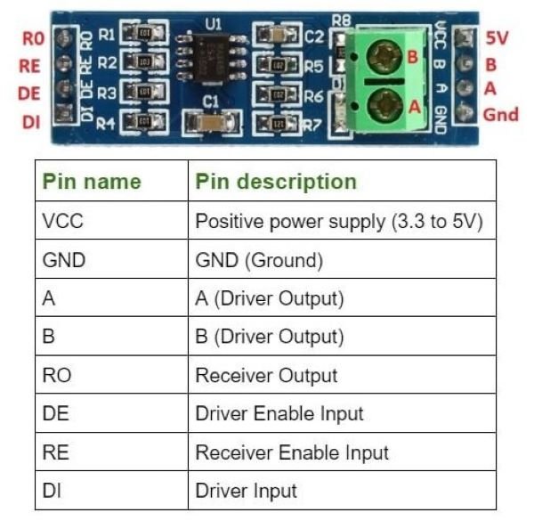
- MAX485 Pinout:
- RO (Receiver Output): Connects to the ESP32 RX pin.
- DI (Driver Input): Connects to the ESP32 TX pin.
- DE (Driver Enable) and RE (Receiver Enable): Controls transmission and reception. Tie these together and connect to an ESP32 GPIO pin to switch between modes.
- A and B: Differential signal lines for RS485 communication.
- VCC and GND: Power supply pins for the module.
- ESP32 Pinout:
- TX (Transmitter Pin): Connects to the DI pin of the MAX485.
- RX (Receiver Pin): Connects to the RO pin of the MAX485.
- GPIO Pin (for DE/RE Control): Used to switch between sending and receiving modes.
- VCC and GND: Provides power to the module.
Step-by-Step Connection Guide
- Power Connections: Connect the VCC pin of the MAX485 module to the 3.3V output of the ESP32 and the GND pin to the ground of the ESP32.
- UART Connections: Connect the DI pin of the MAX485 module to the TX pin of the ESP32 and the RO pin to the RX pin of the ESP32.
- Control Pins: Connect the DE and RE pins together and then to an ESP32 GPIO pin (e.g., GPIO 4) to control transmission and reception.
- RS485 Bus Connections: Connect the A and B pins of the MAX485 to the RS485 bus.
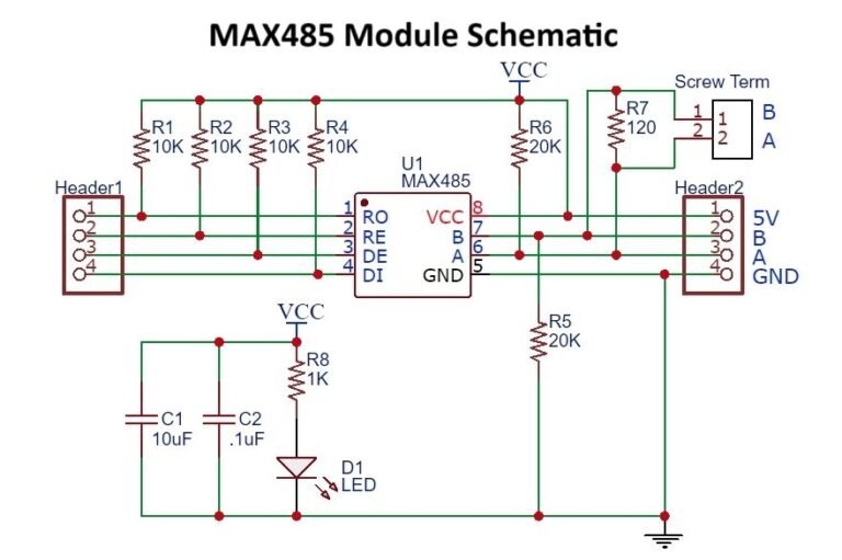
Labeled Circuit Diagram
Diagram showing the connections between the ESP32 and the MAX485 module, clearly labeling each pin.
ESP32 Modbus Communication Setup
Configuring the ESP32 for Modbus Communication
To communicate over RS485 using Modbus, you need to set up the ESP32 to send and receive data using the UART interface. The DE/RE pin must be controlled to switch between sending (DE=HIGH) and receiving (RE=LOW) modes.
Introduction to the Required Libraries
Use a Modbus library compatible with the ESP32, such as “ModbusMaster” for Arduino IDE. This library facilitates Modbus RTU communication, making it easy to read and write Modbus registers.
Software Requirements and Setup
- Install the Arduino IDE or PlatformIO: Ensure you have the ESP32 board configuration installed in the development environment.
- Install Modbus Library: Add the “ModbusMaster” or an equivalent library to your project.
- Configure the UART and Modbus Parameters: Set the baud rate, parity, and stop bits to match the Modbus slave device settings.
- Setup Code for DE/RE Control: Write code to switch the DE/RE pin for proper transmission and reception.
Code Explanation and Implementation
Sample Code for Sending and Receiving Modbus Data Using ESP32 and MAX485
Here is an example code snippet for sending and receiving Modbus data using the ESP32 and the MAX485 module, utilizing the “ModbusMaster” library.
#include <ModbusMaster.h>

// Instantiate ModbusMaster object
ModbusMaster node;

// Define DE/RE pin for MAX485
#define MAX485_DE_RE 4

void preTransmission() {
digitalWrite(MAX485_DE_RE, HIGH); // Enable transmitter
}

void postTransmission() {
digitalWrite(MAX485_DE_RE, LOW); // Disable transmitter, enable receiver
}

void setup() {
// Initialize DE/RE pin
pinMode(MAX485_DE_RE, OUTPUT);
digitalWrite(MAX485_DE_RE, LOW); // Start with receiver enabled

// Initialize Serial for debugging
Serial.begin(9600);

// Initialize Modbus communication baud rate
Serial2.begin(9600, SERIAL_8N1, 16, 17); // Using UART2 (pins 16 and 17)

// Modbus communication settings
node.begin(1, Serial2); // Slave ID: 1
node.preTransmission(preTransmission);
node.postTransmission(postTransmission);
}

void loop() {
uint8_t result;
uint16_t data;

// Read holding register 0x0001
result = node.readHoldingRegisters(0x0001, 1);

if (result == node.ku8MBSuccess) {
data = node.getResponseBuffer(0x00);
Serial.print("Register value: ");
Serial.println(data);
} else {
Serial.println("Communication error");
}

delay(1000);
}
Breakdown of the Code
- Library Inclusion and Global Variable Declaration
- The
ModbusMaster.hlibrary is included for Modbus communication. - The
ModbusMasterobject namednodeis created to handle Modbus transactions. - A constant for the DE/RE pin (
MAX485_DE_RE) is defined to control the MAX485 module’s data direction.
- The
- Setting Up the Modbus Parameters
- The
setup()function initializes the DE/RE pin, the serial port used for debugging, and the UART communication for the MAX485 module. Serial2.begin()sets up UART2 for RS485 communication with a baud rate of 9600, 8 data bits, no parity, and 1 stop bit. The TX and RX pins are defined as pins 16 and 17, respectively.- The Modbus communication is initialized with
node.begin(), setting the slave ID to 1. The functionspreTransmission()andpostTransmission()are set up to control the DE/RE pin.
- The
- Sending and Receiving Data Functions
- In the
loop()function, the code reads from a Modbus holding register (0x0001). - If the reading is successful, the value is printed to the serial monitor. If an error occurs, it prints “Communication error.”
- The delay of 1000 milliseconds ensures the loop runs every second.
- In the
- Specific Configurations for the MAX485 Module
- The DE/RE pin is set to high during transmission (
preTransmission()) and low during reception (postTransmission()). This ensures that the MAX485 module operates in half-duplex mode.
- The DE/RE pin is set to high during transmission (
Testing and Troubleshooting
Step-by-Step Guide to Testing the Communication
- Hardware Testing
- Double-check all connections, especially the RS485 A and B lines.
- Ensure the power supply is stable and correctly connected.
- Use an oscilloscope or multimeter to verify signals on the A and B lines.
- Software Testing
- Upload the code to the ESP32 and open the serial monitor to observe the output.
- Verify the baud rate in the serial monitor matches the configured baud rate in the code.
- Test with different slave IDs and register addresses if communication issues occur.
Common Issues Faced During Interfacing and How to Resolve Them
- No Data Received: Check connections and ensure the DE/RE control pin is toggled correctly.
- Incorrect Data: Verify baud rate, parity, and stop bits configuration. Make sure they match the settings of the Modbus slave device.
- Communication Errors: Use shorter wires for testing to rule out noise interference. Add termination resistors (120 ohms) between the A and B lines for longer cables.
Tips for Debugging Communication Errors
- LED Indicators: Add LEDs to the DE/RE pin or data lines to observe the data flow visually.
- Use Modbus Simulation Software: Tools like ModScan can be used to verify if the Modbus communication works with other devices.
- Try Different Baud Rates: If errors persist, experiment with different baud rates and see if the communication improves.
Applications of MAX485 and ESP32 for Modbus Communication
Examples of Real-World Applications Using RS485 Modbus Communication
- Industrial Automation: Controlling and monitoring industrial equipment like motors, sensors, and PLCs.
- Building Management Systems (BMS): Integrating HVAC, lighting, and access control systems.
- Energy Monitoring: Measuring power consumption, voltage, and current in electrical installations.
- Home Automation: Smart home systems where multiple devices need to communicate over a long distance.
Scenarios Where ESP32 and MAX485 Modules Can Be Used Effectively
- Remote Data Acquisition: Collecting sensor data from remote sites using long RS485 cables.
- Multi-Device Communication: Connecting multiple devices to a single communication bus in a network.
- Automated Process Control: Implementing distributed control systems where the ESP32 acts as a controller for different devices.
Conclusion
In conclusion, Interfacing the MAX485 TTL to RS485 Modbus module with an ESP32 provides a powerful solution for implementing Modbus communication in various applications. The combination allows for reliable data transmission over long distances and multiple device connectivity in industrial, home automation, and monitoring systems. By following the setup and troubleshooting steps outlined in this guide, you can successfully achieve Modbus communication and leverage the ESP32’s capabilities for RS485 applications.
The integration of RS485 communication opens up a wide range of possibilities for automation, data acquisition, and control, making it an essential skill in the field of embedded systems and industrial automation.